Ram 3500 On Board Air Install Photos

alex00

Well-known member
I wanted to give a special "Thank You!" to Al, (DesertThumper) for all his help with this install. He was able to answer all my questions having already done this.

I picked up the Viair Constant Duty air system (part 10007) to use with airbags, and general airing up duty. I installed it this weekend in my 2014 Ram 3500. Hopefully my pictures can help the next person attempting this install.

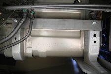
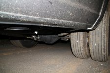
I started by determining the best location for the tank and compressor. I found a spot on the passenger side, under the bed, between the duals and the running board.
001.JPG

The front of the truck is to the left in this photo, I'm on my back, looking straight up. The forward rear spring hanger is just shadowed in this picture. This is the underside of the bed. There are two M12 x 1.75 threaded holes on frame of the bed. They are spaced about 19" apart.
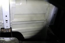
002 (2).JPG

After measuring for the bolt holes, I test fit the plate. The plate measured 10" x 22" with a 3" square cut out of the corner to clear a frame member.
011.JPG

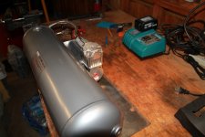
This is the orientation of the tank and compressor on the plate. Once mounted they hang upside down, with the tank on the outboard side.
014.JPG

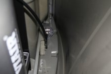
I lucked out with the remote air intake for the compressor. There was a hole already in the sheet metal, between the inner and outer bed skin. This photo is looking forward, inside the passenger side dual fender.
018 (2).JPG

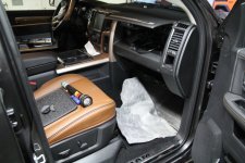
The scariest part of the install was ripping up the carpet and removing the glove boxes. The carpet pulls away easily from the outboard forward corner. It tucks back into place easily, too. I pulled the carpet far enough down to expose the bottom of the thick carpet pad. The lower glove box comes out easily, pull the sides in and tip it forward. There is a little spring loaded string that unhooks from the outboard side of the glove box. The upper glove box has a single screw holding it in on the back. Once removed the liner pops out by pushing it from the back. There are several clips around the perimeter holding it in place. One of these will pop as you push from behind. Unplug the light wire and it is all free.
001 (2).JPG

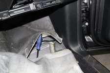
Once I had the carpet pad exposed, I lifted it to access the oval plastic cover. There are several of these covers, but this one is on the slanted portion of the passenger foot well. I wasn't sure how to get it off, but Al assured me it came off with a screwdriver. Sure enough, it pops up, and reveals a very nice hole for getting airlines into the cab. I routed the airlines behind the plastic panel to the right, and up behind the glove box.
006 (2).JPG

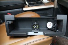
I oriented the air bag gauge at an angle to make it easier to see from the driver seat. I wanted to do the same with the tank gauge, but the back was ugly, and I thought it looked better straight in the middle. I still have half a glove box to use for registration papers if I fill up the lower glove box, or the two giant center console glove boxes.
033 (2).JPG

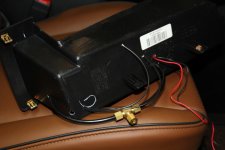
Here is how I plumbed and wired the gauges. I have a single line coming from the tank, it splits to feed the tank gauge and air inlet of the pneumatic switch. I placed the holes for the air lines so the gauges could be positioned as far back as possible. It made drilling and screwing the mounting holes a challenge. I replaced all the Tee fittings with compression fittings from Napa. I did't trust the push-in fittings.
036 (2).JPG

This silver bracket above the blue wire is what holds the upper glove box in place. You can see it by looking up through the lower glove box hole. I used a connector to ground the gauge lights to this bracket. I spliced dome light hot to the yellow wire on the glove box light plug.
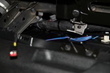
040 (2).JPG

Just before buttoning it all up. All wires are connected and the gauges are plumbed. Even with all the excess air line, it fits together nicely. I had to wrestle the screws in from the air bag gauge over the lip. I didn't realize they were too long until after attaching the barbed fitting.
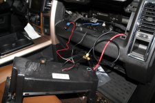
043 (2).JPG

All put back together. I was impressed how solid the gauge and switch feel, despite being mounted to plastic. Even with the tank gauge straight, I have a clear view from the driver seat.
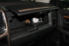
049 (2).JPG

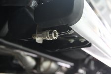
I made a bracket out of scrap steel to mount the air hose coupler to the bottom of the running board.
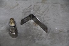
020 (2).JPG

Here is the bracket mounted to the bottom of the running board. There are two screws holding the plastic caps on the end of the running boards. They make the perfect protected and invisible place to run the coupler. You cant see it unless you kneel down.
025 (2).JPG

As far as wiring goes, my Ram has the upfitter switches. Thanks to the advice of others on the forum, I spliced the two positive leads on the pressure switch. Typically the switch is relay powered, triggered by an in-cab switch. I ran a lead from "Aux 3" on the upfitter switch. It is relay powered and protected by 25 amp fuse. I chose this one because it is "last known state" so if I shut the truck off with the switch on, it will be on when the truck restarts. I didn't pretty that wiring up yet since I'm waiting on a few parts. I'm adding an air solenoid to the drain so I can drain the tank from the cab. I'm also adding an air horn.

I ran out of time to install the airbags, but I have a functional, closed air system. Hopefully I'll get the bags in next weekend.
 

DesertThumper

Well-known member
QUOTE=alex00;346501]I wanted to give a speciait "Thank You!" to Al, (DesertThumpit r) for all his help with this install. He was able to answer all my questions having already done this.

I picked up the Viair Constant Duty air system (part 10007) to use with airbags, and general airing up duty. I installed it this weekend in my 2014 Ram 3500. Hopefully my pictures can help the next person attempting this install.

I started by determining the best location for the tank and compressor. I found a spot on the passenger side, under the bed, between the duals and the running board.
View attachment 28426

The front of the truck is to the left in this photo, I'm on my back, looking straight up. The forward rear spring hanger is just shadowed in this picture. This is the underside of the bed. There are two M12 x 1.75 threaded holes on frame of the bed. They are spaced about 19" apart.
View attachment 28428

After measuring for the bolt holes, I test fit the plate. The plate measured 10" x 22" with a 3" square cut out of the corner to clear a frame member.
View attachment 28415

This is the orientation of the tank and compressor on the plate. Once mounted they hang upside down, with the tank on the outboard side.
View attachment 28416

I lucked out with the remote air intake for the compressor. There was a hole already in the sheet metal, between the inner and outer bed skin. This photo is looking forward, inside the passenger side dual fender.
View attachment 28420

The scariest part of the install was ripping up the carpet and removing the glove boxes. The carpet pulls away easily from the outboard forward corner. It tucks back into place easily, too. I pulled the carpet far enough down to expose the bottom of the thick carpet pad. The lower glove box comes out easily, pull the sides in and tip it forward. There is a little spring loaded string that unhooks from the outboard side of the glove box. The upper glove box has a single screw holding it in on the back. Once removed the liner pops out by pushing it from the back. There are several clips around the perimeter holding it in place. One of these will pop as you push from behind. Unplug the light wire and it is all free.
View attachment 28427

Once I had the carpet pad exposed, I lifted it to access the oval plastic cover. There are several of these covers, but this one is on the slanted portion of the passenger foot well. I wasn't sure how to get it off, but Al assured me it came off with a screwdriver. Sure enough, it pops up, and reveals a very nice hole for getting airlines into the cab. I routed the airlines behind the plastic panel to the right, and up behind the glove box.
View attachment 28417

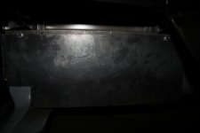
I oriented the air bag gauge at an angle to make it easier to see from the driver seat. I wanted to do the same with the tank gauge, but the back was ugly, and I thought it looked better straight in the middle. I still have half a glove box to use for registration papers if I fill up the lower glove box, or the two giant center console glove boxes.
View attachment 28418

Here is how I plumbed and wired the gauges. I have a single line coming from the tank, it splits to feed the tank gauge and air inlet of the pneumatic switch. I placed the holes for the air lines so the gauges could be positioned as far back as possible. It made drilling and screwing the mounting holes a challenge. I replaced all the Tee fittings with compression fittings from Napa. I did't trust the push-in fittings.
View attachment 28419

This silver bracket above the blue wire is what holds the upper glove box in place. You can see it by looking up through the lower glove box hole. I used a connector to ground the gauge lights to this bracket. I spliced dome light hot to the yellow wire on the glove box light plug.
View attachment 28423

Just before buttoning it all up. All wires are connected and the gauges are plumbed. Even with all the excess air line, it fits together nicely. I had to wrestle the screws in from the air bag gauge over the lip. I didn't realize they were too long until after attaching the barbed fitting.
View attachment 28424

All put back together. I was impressed how solid the gauge and switch feel, despite being mounted to plastic. Even with the tank gauge straight, I have a clear view from the driver seat.
View attachment 28425

I made a bracket out of scrap steel to mount the air hose coupler to the bottom of the running board.
View attachment 28421

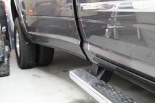
Here is the bracket mounted to the bottom of the running board. There are two screws holding the plastic caps on the end of the running boards. They make the perfect protected and invisible place to run the coupler. You cant see it unless you kneel down.
View attachment 28422

As far as wiring goes, my Ram has the upfitter switches. Thanks to the advice of others on the forum, I spliced the two positive leads on the pressure switch. Typically the switch is relay powered, triggered by an in-cab switch. I ran a lead from "Aux 3" on the upfitter switch. It is relay powered and protected by 25 amp fuse. I chose this one because it is "last known state" so if I shut the truck off with the switch on, it will be on when the truck restarts. I didn't pretty that wiring up yet since I'm waiting on a few parts. I'm adding an air solenoid to the drain so I can drain the tank from the cab. I'm also adding an air horn.

I ran out of time to install the airbags, but I have a functional, closed air system. Hopefully I'll get the bags in next weekend.[/QUOTE]
Your Welcome!!! You did it!!! It looks all to familiar again with the photos. I appreciate you trusting me. The tutorial presented is a 10 plus!

It took time to put this all together with mine being the test run child. But I was assured that this was the recipe and i should suggest a way to make it easier for others or provide ideas. The fittings were a trial an error until i looked back at my previous installs and having friends that work with these air line installs with big rigs, the DOT fittings are the only way to go.

You did a great job and glad to hear you have the air system installed. The gauages look great. I was going to angle mine like your right one, but i ended up switching back to allow lisa be the switch controller except the horn button.... lol. That's on my side with a kill switch for accidental engagement. Lol...

If you decide to run air horns, you will have to T off a seperate line from the bags. If you need suggestions, let me know. I tooted mine on the way home from the high desert with 100 psi in the tank and boy she blew hard.... lol
 

alex00

Well-known member
Your Welcome!!! You did it!!! It looks all to familiar again with the photos. I appreciate you trusting me. The tutorial presented is a 10 plus!

It took time to put this all together with mine being the test run child. But I was assured that this was the recipe and i should suggest a way to make it easier for others or provide ideas. The fittings were a trial an error until i looked back at my previous installs and having friends that work with these air line installs with big rigs, the DOT fittings are the only way to go.

You did a great job and glad to hear you have the air system installed. The gauages look great. I was going to angle mine like your right one, but i ended up switching back to allow lisa be the switch controller except the horn button.... lol. That's on my side with a kill switch for accidental engagement. Lol...

If you decide to run air horns, you will have to T off a seperate line from the bags. If you need suggestions, let me know. I tooted mine on the way home from the high desert with 100 psi in the tank and boy she blew hard.... lol

It was definitely helpful having your rig as the guinea pig. I'm really glad you told me about the fittings from Napa. After looking at the stock fittings, there is no way I'd trust them to be leak free in an area that was hard to get to.

What I really want to do is have a plastic panel made to hold both gauges and the switch inside the glove box, that completely hides the wires and tubing. I know this is fine, but just for looks, I think that would be a nice finishing touch.

I have a dual fitting I bought that "Ys" at the tank so I can run the air line to the horn. My concern right now is if I use the dash switch, since it is so easy to run 1 wire and be done, or install a momentary switch. I know I really want a momentary switch inside the big bucket thing in the center console. I can reach it easily there as I drive. However... If I use the dash switch, I could blast a whole tank of air, hands free. I'm not saying I'd be "waiting" for someone to cut me off in traffic, but...
 

DesertThumper

Well-known member
The panel would be a great add on. Maybe something to do next. Even a nice piece of sheet metal. They have the gauge rack you can buy that mounts on the left side post of your front windshield. Hiding it seems to be a better fit though for me.

You have a great plan for your air horn add on. The bag install will be gravy for you. I use thread lock - the red color in a blue tube.

Love to see more pics when you get your bags and horn installed.
 

porthole

Retired
I have a dual fitting I bought that "Ys" at the tank so I can run the air line to the horn. My concern right now is if I use the dash switch, since it is so easy to run 1 wire and be done, or install a momentary switch. I know I really want a momentary switch inside the big bucket thing in the center console. I can reach it easily there as I drive. However... If I use the dash switch, I could blast a whole tank of air, hands free. I'm not saying I'd be "waiting" for someone to cut me off in traffic, but...

Thoughts on the air horns.

On my truck I have the air horn solenoid wired to the electric horn. But, I have an on-off switch on the dash so the air horns only operate when I want them (towing).

I currently have the solenoid mounted on the tank. I plan on moving that to the horns. Not sure how much of change it will be, but I figure it ought to help since I have about 15' of 3/8" hose from the tank to the horn. My horns are mounted in the front grill.

And since someone gave me another set of horns, hopefully in the spring I can really make the little Ford sound big :cool:

I use thread lock - the red color in a blue tube.

Just an FYI, Loctite makes a thread locker - sealant specifically for air and hydraulic fittings.

http://www.amazon.com/Loctite-Pneum...054048&sr=8-8&keywords=air+line+thread+sealer
 

alex00

Well-known member
Thoughts on the air horns.

On my truck I have the air horn solenoid wired to the electric horn. But, I have an on-off switch on the dash so the air horns only operate when I want them (towing).

I currently have the solenoid mounted on the tank. I plan on moving that to the horns. Not sure how much of change it will be, but I figure it ought to help since I have about 15' of 3/8" hose from the tank to the horn. My horns are mounted in the front grill.

And since someone gave me another set of horns, hopefully in the spring I can really make the little Ford sound big :cool:


Just an FYI, Loctite makes a thread locker - sealant specifically for air and hydraulic fittings.

http://www.amazon.com/Loctite-Pneum...054048&sr=8-8&keywords=air+line+thread+sealer

Duane thanks for the heads up on the thread sealant. I need to chase down a slow leak. I left the tank charged for an hour and noticed a 10ish psi drop.

I hadn't really thought about wiring my air horn to the main horn. That's a way of doing it that I need to consider. It would be much easier than running a new momentary switch into the cab.

Do you notice the stock horn at all when blowing the air horn, or is it so loud it doesn't matter?


Sent from my SAMSUNG-SGH-I747 using Tapatalk
 

porthole

Retired
Duane thanks for the heads up on the thread sealant. I need to chase down a slow leak. I left the tank charged for an hour and noticed a 10ish psi drop.

I hadn't really thought about wiring my air horn to the main horn. That's a way of doing it that I need to consider. It would be much easier than running a new momentary switch into the cab.

Do you notice the stock horn at all when blowing the air horn, or is it so loud it doesn't matter?

From in the cab, I can clearly hear the stock horn.

I still ran wires. I took the feed right off the horn. Used 10 gauge (cause i had it), back to the cab for the on-off switch and then to the solenoid on the tank.
 

alex00

Well-known member
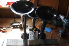
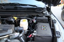
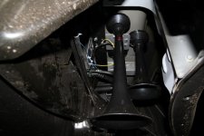
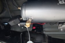
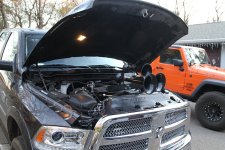
I finished up the horn install this afternoon. I tucked it up into the driver side dually fender. I used the same M12 holes on the driver side to fasten a 3" x 22" plate to the underside of the bed. I mounted the horn bracket to the plate, and it all tucks up nicely. The longest of the three horn trumpets sticks about 1/2" below the body, but you can only see it when you are on the ground. I bought, but have not installed a momentary switch for the horn. I am debating the best location for the switch, so for now, I am just activating the horn with the upfitter dash switch. I bought a fancy stainless switch with blue LED light ring. I am probably going to save that for something else and get a normal unlit button, because the mounting spot I'd like to use isn't really visible. I wrapped all the wires heading to the tank area with wire loom and buttoned it up for a more factory look under the hood.

022.JPG027.JPG028.JPG039.JPG040.JPG


I also installed a solenoid on the air tank drain fitting, to burp or bleed the tank from the cab. No more reaching under the truck to drain the tank after each use. Of the five upfitter switches, I've used three. One for the air compressor, one for the horn and one for the tank drain, leaving two 40 amp switches for future lights.

030.JPG
 

alex00

Well-known member
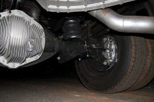
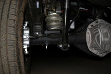
I finished up the entire install today. I installed the air springs. That was much easier than I imagined. I filled them up to 70 PSI after the install and no leaks. They are holding pressure really well. I think using the brass compression fittings instead of the press fittings included with the kit made a difference.

027.JPG032.JPG

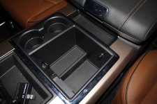
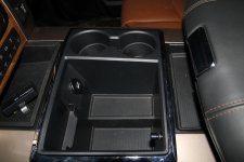
I added a momentary switch for the horn. I placed it in the big center cubby hole, because my hand naturally rests there when I drive. I can press the button without having to reach or aim for a button on the dash. I still trigger the whole horn system from the upfitter switch, but send it all to a second relay, controlled by the momentary switch. This momentary switch from Radio Shack takes a bit of effort to trigger. I really wanted something that wouldn't trigger too easily if bumped by something in the cubby.

025.JPG021.JPG

I had to really work at stopping the leaks after adding the automatic tank drain. That thing would not seal to save my life. I ended up pulling it all apart and adding about 6 inches of teflon tape. That and renting a gorilla to tighten it on, made the leak go away.
 

alex00

Well-known member
Awesome! Looking good. Did you get a chance to test your horn? Glad your bags went well.

Thanks Al, yes I did a little testing :angel:...

After the first blow, I realized there was no way I was going to do that again in my driveway. My neighbors would kill me. I drove out to the middle of nowhere and blasted away. Man that thing is loud, I think it goes to 11. My seven year old loves the horn.


033.JPG
How bad do I really need the hood to close all the way?
 
Top