Garypowell
Well-known member
I had installed a 32 gallon aux fuel tank in my 2008 Chevy the last couple of years of my ownership. Purchased a 2015 3500 Silverado HD SRW late last year and before the trade in I removed the Aux Tank.
To my surprise the 2015 had a 36 gallon tank instead of the 26 I had in the previous truck. But the aux tank was still an attractive thing to have as it would give me a 58 gallon capacity. This year we are going out to Utah and back and this added capacity will come in handy.
Frankly, I never liked the gravity feed. It took too long……most of the day sometimes. Began searching this forum for pump solutions and found many great threads….but not many that had pictures of what was done. So I have taken some pictures and comments on the process.
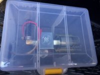
First, I researched and found the Facet Electronic Fuel Pump model 40257. It has a max capacity of 25 GPH, is 12 volt and has an internal check valve so no flow when off.
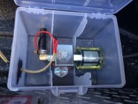
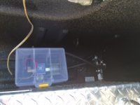
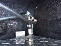
I simply cut the fuel line right after the aux tank valve and then piped the supply and return lines back to the box that held the pump. If the pump ever fails I can simply remove these added lines and join the original lines back at the cut to return to gravity feed.
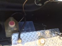
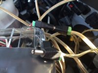
You can also see an overall shot of the piping (fairly dark), the pump box, and my overflow tank sitting beside the Aux Tank. I have also included a close up of the box and with the lid open. While this box is not weather proof I think it will do fine as it is. You can see the fuel filter that I purchased with the pump also, and power cord coming from the engine compartment.
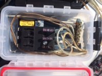
I had already installed an extra fuse box that is hooked right to the battery. It powers my bed lighting, the GPS, and TPMS inside of the truck. If you saw my other thread of looking for the “ignition side” of my electrical system you’ll know it took me at least a week to find it. So in the meantime, wanting to use this new set up I went ahead and added another circuit that could power the pump full time.
I thought I might remove this full time power supply but then thought better of it. If something happened to my fuse tap system it would be a good emergency power source for the pump….or anything else for that matter.
The main concern I had over the pump having the potential to have power all the time was burning out the pump (which the manufacturer said was a possibility). This is why I wanted to have a power source that would shut off with the trucks ignition.
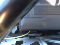
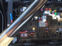
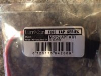
Finally figuring out the correct size of fuse tap you can see it installed in the trucks fuse box. I decided to install it in the fog lamp circuit. Being way over cautious but this puts another layer of security in the system in that you have to have the fog lights on to pump fuel. I did not want to break into anything critical on the truck…..like ABS system, etc.
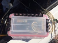
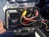
The main reason for all this caution is that I decided to use a 315 MHz relay to turn the pump on and off. 315 MHz is the frequency garage door openers use. My truck is equipped with 3 garage door opener buttons but no up-fitter switches. Only having one garage door switch in use left the other two available. One is used to turn the pump on and the other is to turn the pump off.
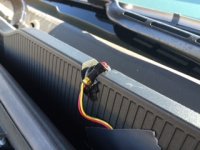
You can see in the remaining pictures the pump relay box, the fact that there are two power supplies. Right now the ignition one is plugged in.
You can also see a nifty indicator light that is glued right above the windshield washer nozzle on the driver’s side. Any time the pump is activated this red light flashes and I can easily see it.
Fun project but took too long to accomplish. We are leaving this Friday for a 6 week trip and am glad I got this accomplished.
To my surprise the 2015 had a 36 gallon tank instead of the 26 I had in the previous truck. But the aux tank was still an attractive thing to have as it would give me a 58 gallon capacity. This year we are going out to Utah and back and this added capacity will come in handy.
Frankly, I never liked the gravity feed. It took too long……most of the day sometimes. Began searching this forum for pump solutions and found many great threads….but not many that had pictures of what was done. So I have taken some pictures and comments on the process.
First, I researched and found the Facet Electronic Fuel Pump model 40257. It has a max capacity of 25 GPH, is 12 volt and has an internal check valve so no flow when off.
I simply cut the fuel line right after the aux tank valve and then piped the supply and return lines back to the box that held the pump. If the pump ever fails I can simply remove these added lines and join the original lines back at the cut to return to gravity feed.
You can also see an overall shot of the piping (fairly dark), the pump box, and my overflow tank sitting beside the Aux Tank. I have also included a close up of the box and with the lid open. While this box is not weather proof I think it will do fine as it is. You can see the fuel filter that I purchased with the pump also, and power cord coming from the engine compartment.
I had already installed an extra fuse box that is hooked right to the battery. It powers my bed lighting, the GPS, and TPMS inside of the truck. If you saw my other thread of looking for the “ignition side” of my electrical system you’ll know it took me at least a week to find it. So in the meantime, wanting to use this new set up I went ahead and added another circuit that could power the pump full time.
I thought I might remove this full time power supply but then thought better of it. If something happened to my fuse tap system it would be a good emergency power source for the pump….or anything else for that matter.
The main concern I had over the pump having the potential to have power all the time was burning out the pump (which the manufacturer said was a possibility). This is why I wanted to have a power source that would shut off with the trucks ignition.
Finally figuring out the correct size of fuse tap you can see it installed in the trucks fuse box. I decided to install it in the fog lamp circuit. Being way over cautious but this puts another layer of security in the system in that you have to have the fog lights on to pump fuel. I did not want to break into anything critical on the truck…..like ABS system, etc.
The main reason for all this caution is that I decided to use a 315 MHz relay to turn the pump on and off. 315 MHz is the frequency garage door openers use. My truck is equipped with 3 garage door opener buttons but no up-fitter switches. Only having one garage door switch in use left the other two available. One is used to turn the pump on and the other is to turn the pump off.
You can see in the remaining pictures the pump relay box, the fact that there are two power supplies. Right now the ignition one is plugged in.
You can also see a nifty indicator light that is glued right above the windshield washer nozzle on the driver’s side. Any time the pump is activated this red light flashes and I can easily see it.
Fun project but took too long to accomplish. We are leaving this Friday for a 6 week trip and am glad I got this accomplished.
Attachments
-
 10.Power wire out of truck fuse box.jpg27 KB · Views: 60
 -
 9.Fuse Tap installed.jpg37.5 KB · Views: 60
 -
 8.Fuse Tap package.jpg32 KB · Views: 63
 -
 7.Aux fuse box open.jpg38.5 KB · Views: 60
 -
 6.Aux fuse box.jpg30.3 KB · Views: 60
 -
 5.Overall overflow, pump, piping.jpg29.3 KB · Views: 60
 -
 4.Pump in box.jpg35.7 KB · Views: 62
 -
 3.Pump Box.jpg28.2 KB · Views: 60
 -
 2.Pump and Piping.jpg30.3 KB · Views: 57
 -
 1.Piping.jpg44.1 KB · Views: 60
 -
 13.Pump on indicator Lamp.jpg34.5 KB · Views: 68
 -
 12. 2 power supplies for pump.jpg35.2 KB · Views: 67
 -
 11.Pump controller.jpg43.3 KB · Views: 64