Coax Diagram

BobbyandGenee

Well-known member
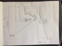
Because this is a new unit, my dealer was going to charge me by the hour to figure out the Coax configuration, and Heartland did not have a configuration file. So I did it myself and I am sharing it with everyone (including my dealer and Heartland). Notice i found that the splitter behind the faceplate in the master bedroom is wired a little odd (in my opinion). If someone was going to have an input from outside the splitter connections need to be moved around. Also, a portable satelittle could be used into the external input, but would require reworking the splitter and probably adding a dual coax faceplate.
IMG_4903.jpg
 

wdk450

Well-known member
Because this is a new unit, my dealer was going to charge me by the hour to figure out the Coax configuration, and Heartland did not have a configuration file. So I did it myself and I am sharing it with everyone (including my dealer and Heartland). Notice i found that the splitter behind the faceplate in the master bedroom is wired a little odd (in my opinion). If someone was going to have an input from outside the splitter connections need to be moved around. Also, a portable satellite could be used into the external input, but would require reworking the splitter and probably adding a dual coax faceplate.
View attachment 51459

I think that your drawing could use some more labels on terminations. Also, as far as the splitter being wired a little odd, simple splitters form a Y connection so that 3 points are wired together. Input/output means nothing on these. Satellite/TV splitters (diplexers) which have frequency dividing networks in them are another matter.
 

BobbyandGenee

Well-known member
I think that your drawing could use some more labels on terminations. Also, as far as the splitter being wired a little odd, simple splitters form a Y connection so that 3 points are wired together. Input/output means nothing on these. Satellite/TV splitters (diplexers) which have frequency dividing networks in them are another matter.
Absolutely

This was meant as a "jumping off point" diagram. We have to dismantle all the face plates and iRV radio to trace all the coax. At least that hard part is solved. When i have time i will draw up a nice "outline" of the Trailer with connection points and labels.

This all got started because nothing was working when we got it home. After taking it all apart, we found out that most of the terminals were no screwed in, or where very loose and not making connections. So i figured while i had it all apart that would be a good time to make a diagram. :)
 

wdk450

Well-known member
Absolutely

This was meant as a "jumping off point" diagram. We have to dismantle all the face plates and iRV radio to trace all the coax. At least that hard part is solved. When i have time i will draw up a nice "outline" of the Trailer with connection points and labels.

This all got started because nothing was working when we got it home. After taking it all apart, we found out that most of the terminals were no screwed in, or where very loose and not making connections. So i figured while i had it all apart that would be a good time to make a diagram. :)


Bobby:
You might want to look through the coax layout diagrams on this website to find something the same or very similar to what you have. The diagrams are found on the "Tools" tab, then "Manuals", "Electronics", and "Coax Layouts" in the submenus. Here is a direct link to the coax layouts page: https://manuals.heartlandowners.org/?man=/Electronics/Coax_Layouts/All_Brands
 
Top