‘12V’ Automatic Resetting Circuit Breakers

ram22

Well-known member
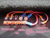
My ‘15 North Trail 22FBS has 3 of these bussed together and attached to the frame near my ‘paralleled’ 12V batteries and battery isolator switch. Two of them are labeled 12V 30A and one labeled 24V 50A. Does that sound right? They are all three connected by a copper bus bar at one end. The other ends appear to go to battery isolator switch, tow vehicle, converter/distribution panel. My WFCO Converter with Distribution Panel is labeled Panel Input 120 VAC 30A, Converter Input 105-130 VAC 12A, Converter Output 13.6VDC 55A. I am troubleshooting my electric slide which intermittently loses electrical power. I am considering replacing these 3 c/b’s as an inexpensive troubleshooting step. That’s a topic for somewhere else. Here, I am just trying to determine if these c/b’s are rated properly.
e363e362bcb9526e76769925f52e78e8.jpg
cbcbd857885cb50a09bb9e3cd17dad9f.jpg
c96f43caf725af1d958bb59212cfa398.jpg


Sent from my iPhone using Tapatalk
 

danemayer

Well-known member
There's usually a 50 amp manual reset breaker between the battery and the Power Converter. The 30 amp breakers are probably auto reset.

For the slide problem, you might take a look at our Hydraulic Slideout Starts and Stops user guide. The Electrical user guide in that folder may also be helpful.
 

ram22

Well-known member
There's usually a 50 amp manual reset breaker between the battery and the Power Converter. The 30 amp breakers are probably auto reset.

For the slide problem, you might take a look at our Hydraulic Slideout Starts and Stops user guide. The Electrical user guide in that folder may also be helpful.

Thanks for that link. I will definitely be reading that. Regarding these c/b’s, here is another photo with the one 50A on the right. Does that look like manual reset? If not, should it be? Would be nice to manually reset for troubleshooting since the auto c/b’s apparently cool down over time before they reset themself.
828d73e05e9c026fd6d710063ad850c8.jpg


Sent from my iPhone using Tapatalk
 

mlpeloquin

Well-known member
The 50 amp, if it is manually reset, should have a little black button on the opposite side that is shown in your picture. That is the side with the buss bar. reach under or use a mirror to see it.
 

danemayer

Well-known member
Looking at wire size, I would think the breaker on the left goes to the power converter and would have the reset button.

Sent from my SM-G950U using Tapatalk
 

ram22

Well-known member
The 50 amp, if it is manually reset, should have a little black button on the opposite side that is shown in your picture. That is the side with the buss bar. reach under or use a mirror to see it.

You’re right! I could barely see it with a mirror and flashlight but I can find it now with my finger tip. WTH didn’t they install that thing upside down?


Sent from my iPhone using Tapatalk
 

ram22

Well-known member
Looking at wire size, I would think the breaker on the left goes to the power converter and would have the reset button.

Sent from my SM-G950U using Tapatalk

Actually, if you look closely at that photo you’ll see an eyelet connector coming down from above and that wire gauge looks the same as the wire you see on the left of the photo. The wire on the left goes to the battery isolator switch.
I did find a small black reset button on top of the c/b (labeled 50A) on the right.


Sent from my iPhone using Tapatalk
 

ram22

Well-known member
There's usually a 50 amp manual reset breaker between the battery and the Power Converter. The 30 amp breakers are probably auto reset.

For the slide problem, you might take a look at our Hydraulic Slideout Starts and Stops user guide. The Electrical user guide in that folder may also be helpful.

I read both. Very interesting. Did you see my reply that a heavy gauge wire is hidden from view on the 50A c/b on right side of photo? The 30A c/b on left side of photo goes to battery isolator switch. So my next question is which of those 3 c/b’s supplies power to the electric slide? Is that the smaller gauge wire on the 50A c/b? In that case, that 50A c/b is carrying the combined load of operating slide and converter. Replacing those c/b’s is recommended for troubleshooting. How about if I just add one for the slide only? If I did that, does the electric slide need a 50A c/b? Both of the documents you referenced talk only about the hydraulic slide motor needing 50A.


Sent from my iPhone using Tapatalk
 

danemayer

Well-known member
I'm not sure what you've got. The hidden wire at the top right is powering the breaker it's attached to, and the other breakers through the copper buss bar. That hidden wire would typically go to the battery. But you say the wire from the other side, on a 30 amp breaker, goes to the battery cutoff.

I don't think North Trails typically come from the factory with a battery cutoff switch. So perhaps the wiring was changed when the cutoff switch was added.

If the battery power is coming through a 30 amp breaker, and a buss bar, then the maximum power available to the hydraulic pump is 30 amps. And the maximum from battery to the fuse box inside the trailer is 30 amps. And the maximum from the Power Converter to the battery is 30 amps.

That leads me to wonder why there's a 50 amp breaker and what it's feeding, and what good it's 50 amp rating is doing.

I think you'll need to trace all the wires to see where they go.

828d73e05e9c026fd6d710063ad850c8.jpg
 

ram22

Well-known member
I'm not sure what you've got. The hidden wire at the top right is powering the breaker it's attached to, and the other breakers through the copper buss bar. That hidden wire would typically go to the battery. But you say the wire from the other side, on a 30 amp breaker, goes to the battery cutoff.

I don't think North Trails typically come from the factory with a battery cutoff switch. So perhaps the wiring was changed when the cutoff switch was added.

If the battery power is coming through a 30 amp breaker, and a buss bar, then the maximum power available to the hydraulic pump is 30 amps. And the maximum from battery to the fuse box inside the trailer is 30 amps. And the maximum from the Power Converter to the battery is 30 amps.

That leads me to wonder why there's a 50 amp breaker and what it's feeding.

I think you'll need to trace all the wires to see where they go.

828d73e05e9c026fd6d710063ad850c8.jpg

Ohhhh! Now I’m getting somewhere. So, you’re right about the cutoff switch. I paid the dealer to install the battery isolator switch and second battery before I took delivery. Here’s another photo where you can clearly see the battery isolator switch connected to the far side c/b. You should be able to read that c/b stamped 30A. The c/b stamped 50A (stamping not visible) also has a heavy gauge wire (the hidden one) going up and into a conduit but appears to go aft into the trailer and ‘toward’ the converter. Of the two wires coming down, from the near side c/b that one goes forward to the tow vehicle connection, and from the middle c/b that one also appears to go aft into the trailer. Maybe that middle c/b red wire goes to the slide motor. I could disconnect it to find out. Meanwhile, my next question, like yours, is why is there a 50A c/b and what rating c/b does my slide motor require? If you can tell me that much, I will call my dealer and ask about their installation. I don’t see any of those documents in the link addressing the electric slide.
c7f020f8de23a3430c339e864cefdefd.jpg


Sent from my iPhone using Tapatalk
 

ram22

Well-known member
Here’s another photo just meant to show that all three c/b’s are tied together by a copper bus bar. The heavy gauge cable on the left goes to the isolator switch and batteries. So, the top posts of these 3 c/b’s are all connected to the batteries when the isolator switch is closed. The heavy gauge cable not visible in this photo, going up from the c/b on the right, is attached to the top post. Where would that heavy gauge cable go if it is powered by the batteries anytime the isolator switch is closed and having no c/b protection here? Would that hidden wire probably go to the converter?
A couple things seem wrong here, comparing my dealer modified wiring to the block diagram.
One, the battery isolator switch should be connected to the other post of the c/b it is connected to, the same post as the tie bar. Right?
Second, if that ‘hidden’ (from view in the photo) wire goes to the converter, it should be on the other post so that the 50A c/b protects that circuit. Right?
Isn’t that what the Heartland ‘typical’ DC block diagram shows?
f5547556b5a16cd50624a1bb8a84e5a7.png

8a3d65dc0652a90a3cb3981c566e4dae.jpg


Sent from my iPhone using Tapatalk
 

danemayer

Well-known member
The hydraulic pumps on larger trailers require 50 amps. I don't know what size pump your North Trail uses. It might be ok with 30 amps. Or not. Look at the hydraulic pump wires, at the pump end. If it's powered via a thinner wire, it probably only needs 30 amps. If a fat wire, probably 50 amps.

I've attached a picture from a Landmark. Notice that the battery connection goes to the side of the breaker with the buss bar, spreading the battery power to all breakers. And the Power Converter connection, a thick wire, meets the battery power at the manual-reset breaker.

I'm not saying it can't be made to work the way yours is wired, but my first guess is the wires were disconnected and put back wrong. Or maybe the breakers/buss bar was taken off and put back flipped left-to-right.

At this point, we're guessing. I think you're going to have to trace wires to know for sure what each wire does.
 

Attachments

  • Buss Bar Example Notated.jpg
    Buss Bar Example Notated.jpg
    174.8 KB · Views: 26
Top