Progressive Dynamics PD1200 Inverter Install Question

6.7LMegaCab

Well-known member
After going back and forth on deciding a route to take with a new converter and getting an inverter, I decided to stick with PD. At this time, we don’t need a whole lot of AC power when the Gen or Shore power is disconnected, thus the reason for the 1000W inverter.

With that in mind, I decided to get the 1000W inverter from PD. Since it has a built in transfer switch, I’m slightly confused on how to wire it in based on the wiring diagram from the install guide.

This is my current setup:

Cummins/Onan 5500W GenSet
Shore Connection
PD52DCS 50A Auto Transfer Switch
PD9260 Converter (to replace the WFCO 9855)
WFCO 8930/50 AC/DC Distribution Center
4x US Battery US 2200 XC2 6V 232AH Batteries

Ideally, I’d like to hardwire the Inverter to one side of the Distribution Center, but still have that side operating on shore or gen power.

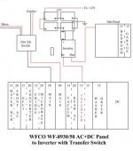
Would it be appropriate to take one side of the hots (red or black) from the PD52 transfer switch and wire it to the AC-In of the inverter and run the same size wire from the AC-Out to one of the 50A main breakers? We will not be running the Air Conditioner while on battery.

Here is a diagram I drew up of what I think it would look like:

Progressive Dynamics Inverter Wiring.jpg

I appreciate any feedback to make this right, the first time.

Also, any recommendations on a DC fuse or circuit breaker for the battery side is greatly appreciated.

Actually, I just read the install instructions again...there is a 15A breaker built in, so I obviously can’t connect directly from the PD52 Transfer Switch to the breaker box. So the diagram above will not be appropriate, any recommendations to wire it would be greatly appreciated. I guess what doesn’t make sense is how to provide power to one side of the AC bus bar while on the Inverter and still allow Gen or Shore power on that side.

The install guide shows all three connected on one side of the distribution center.


Thank you!

-Josh
 
Last edited:

6.7LMegaCab

Well-known member
Alright! So to hopefully help others out, I finally figured out why PDs install guide was so confusing: the AC Distribution Panel they used in their diagram is a 50/30 split panel and they are using a 15A breaker connected from 50A side through the inverter input back to the sub panel side through another 15A breaker.

It would have been nice if they actually mentioned it was a 50/30 panel instead of just showing a part number and how to connect to a 50A panel.

So with that said, I think I figured out the best way to wire it. This should also work for other inverters with a built in transfer switch. I still don’t think it’s wise to combine a charge converter/inverter/transfer switch into one unit like some of the recommended units are setup. Just seems an expensive piece to replace if one side dies. Plus, I think sticking with Made in the USA products helps keep things here. Perhaps PD will recognize that need as well and step up with a larger inverter.

Back to the wiring.

15A from main AC panel to the AC Input of the inverter

Inverter AC Output will go to a sub-panel where I’ll run the one or two outlet only circuits too.

The benefits of doing it this way is that shore or generator power will still be available to those circuits that were relocated to the sub panel. In the future if I find myself needing more inverter power (I really don’t think I will, but only time will tell), I’ll be able to upgrade the circuit breaker in the main panel to a 30A that feeds through a new inverter (if it has a built-in 30A transfer switch).

One key take away when purchasing an inverter with a built-in transfer switch is to find one that matches your AC panel. Doing so would allow you to run one of the legs directly through the inverter and back to the AC panel without needing to run a sub-panel.
 

Attachments

  • Progressive Dynamics Inverter Wiring 2.jpg
    Progressive Dynamics Inverter Wiring 2.jpg
    20.3 KB · Views: 16

danemayer

Well-known member
The PD1200 50 amp diagram is a little confusing. But the labeling at the bottom of the diagram helps. I don't understand your comment about it being a 50/30 panel. It looks to me like it's showing a PD55 breaker panel with a 50 amp main bus and a 15 amp sub panel bus.

Unlike the PD55, your equipment list shows a WFCO 8930/50 distribution panel that looks like it has a single bus with no sub panel. So your 2nd diagram adds a sub panel to take the 15 amp output of the PD1200.

Yes, that should power those 2 circuits, with the PD1200 internal transfer switch switching to inverter output when not getting power from the main breaker panel. And by using a sub panel, you avoid the problem of battery power going to the Power Converter and then back to the battery.
 

6.7LMegaCab

Well-known member
The PD1200 50 amp diagram is a little confusing. But the labeling at the bottom of the diagram helps. I don't understand your comment about it being a 50/30 panel. It looks to me like it's showing a PD55 breaker panel with a 50 amp main bus and a 15 amp sub panel bus.

Unlike the PD55, your equipment list shows a WFCO 8930/50 distribution panel that looks like it has a single bus with no sub panel. So your 2nd diagram adds a sub panel to take the 15 amp output of the PD1200.

Yes, that should power those 2 circuits, with the PD1200 internal transfer switch switching to inverter output when not getting power from the main breaker panel. And by using a sub panel, you avoid the problem of battery power going to the Power Converter and then back to the battery.


I had to look up the part number for PDs power distribution panel. It can come configured as a 50A with a 30A sub built into it.

https://www.progressivedyn.com/rv/acdc-distribution-panels/pd5500-series-ac-distribution-panel-50-amp-240-vac/

The diagram labeling was confusing as well. I know it says sub, but until I looked up that part number, I had no idea you can get a 50/30A split distribution box.

I thought they made a mistake with the labeling because the diagram looks like a standard AC box. Thus the reason for the original post because I was confused as can be because to me it looks like it created a very dangerous loop.

My WFCO is split in the middle, so it has a bus on both sides. After I bought my rig a couple years ago, it took me until a few weeks ago to figure out why one of the 30A breakers on the generator kept tripping, mainly when running both A/C units. They were both wired on the left side. I moved the converter to the left side and one of the A/C units to the right side, and now I am able to run both units plus the microwave with no problems on the generator. There were issues with shore power as well, which I think led to the original transfer switch failing (PD52). It was replaced with another PD52 with the remote display.

The only other way I could have hooked it up on the right bus was by getting another transfer switch. I found that out by accident when I discovered another 50A plus inverter diagram buried at the bottom of PDs FAQs. That defeated the purpose of keeping it simple.

Oh! BTW, I stumbled across your website from another buried post on here. What a huge source of information! Sadly, it didn't solve my confusion until I looked up PDs distribution boxes.

Thank you for the reply... and your website. I have it saved as a favorite.
 
Top