mlpeloquin
Well-known member
The following discrepancies were found after a close inspection of my fifth wheel. I missed out on the Southern California rally at Pechanga Resort in Temecula, California when I broke my leg. Bob and Patty do a really nice job with the Southern California Rally and kick myself hard for having to miss the rally. Pechanga is really a nice RV park. This gave me a lot of time to read the form and see what things have cropped up over time in other owners rigs. These discrepancies are not isolated to Heartland products. Look at other blogs and you will see that.
I first looked at the main electrical wiring going into the rig. My Big Horn has a power real. Would not want to be with out it, but an inspection is mandated of you do not want to potentially destroy all the electronics in it or create an electrical fire. Note if you don”t have a power reel, you need to inspect the connections on the back of the RV power connector. It too can have loose connections and cause the same to happen. A loose neutral in the power reel seems to crop up over time. Shake and vibe loosens screws and nuts. To inspect the power connections unplug your electrical cord and pull all of it out of the reel box. This will expose the screws that hold the access panel on. On screw and open the panel. It is spring loaded so when putting it back on, don’t tighten the screws up until all of them have been started.
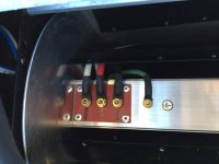
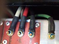
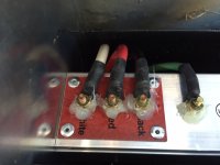
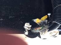
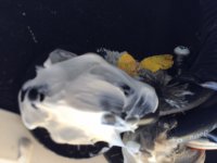
At first glance it looked good, but when I pushed on the white neutral connections it was very loose. In fact it rattled when moved up and down. The red hot was easy to move, but was sort of almost tight. The rest were tight and would not budge at all. I tightened the loose nuts. Be careful since the threaded studs and nuts are brass. I then applied Loctite between the nut and the stud threads after tightening. Do not use Loctite under the threads here since you do not want to isolate the good mechanical/electrical connection. (I know the pictures are upside down, but I have not figured out how to rotate them.
I took the picture when the Loctite was wet so it would show up in the picture. Do not use penetrating Loctite or an un-removable type. In the aerospace industry, Cab-o-cil, untreated fumed silica which is mixed with uralane conformal coating, is used to absorb shock and vibrations. It requires a bake-out, so it is not practical here, but RTV silicone will work in this application. Apply it on the sides of the nuts to the base. Do not get it on the stud threads. If you do, it will make it more difficult to remove the nuts if necessary in the future. A silicone release agent would have to be used.
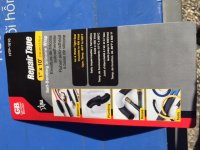
Next I looked at the electrical junction boxes under the slides. Several people reported that the wire nuts had come loose and created an open or high resistance connection. I found only one that was ready to fall off. All others were tight. This is what I did to insure that they don’t. I purchased a self-sealing silicone tape. After it is on for a few days, it will have to be cut off to remove it. There are at least two manufactures of this tape. This is the one I used. It can be purchased at Orchard Supply Hardware, Lowe's and other stores.
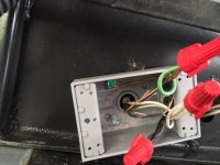
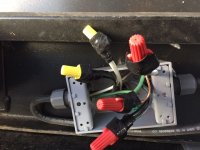
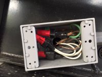
I did the junction boxes under each slide the same.
This gave me a chance to look at how the electrical wiring is routed under the slide. Oh boy! I am glad it was the green ground that was exposed. The cable makes a sharp 90 degree turn into the slide wall from underneath. This is what I found.
I looked at what might have caused this. When the slide is in, the cable is inside the under side of the fifth wheel floor. There is a rubber water seal at first glance that should not and could not remove the white RTV silicone and insulation of the cable. I pulled back the rubber seal and it revealed a metal backing that was slightly bent. Not enough to allow the wire and silicone that Heartland put on to clear it. On the way in it would just rub, but on the way out it is a sharp cutting edge that grabbed and cut the silicone and cord insulation.
I bent the metal enough to clear the cord and new insulation.
The cord was wrapped with the self-sealing waterproofing tape I used to secure the wire nuts. Then I cover all of it with white silicone RTV.
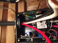
I have been using and will continue to use an external Sure Guard Protector, but added an internal Progressive Industries 50 Amp surge, voltage, and open neutral protector. On my Big Horn 3010RE, there was not any room to mount it on the floor of the basement. The studs were perfectly spaced to allow it to be mounted between them. This would make the cable too short so I ordered wire from Home Depot and shrink sleeving from DigiKey Electronics. I used strain reliefs on the input cable as well as the new output cable screwed into the studs. If you notice the input cable is six gauge wire, and the output cable is four gauge wire. Electrical code requires 4 gauge wire for 50 amps in electrical building wire applications. In box unit/appliance wiring, the code calls out 6 gauge wire. I guess RV manufactures believe the RV’s are box/appliances. So you could use 6 gauge. The cost difference is small.
INPUT
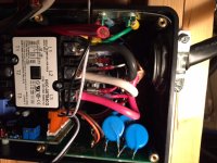
Used the same silicone tape to build up the insulation for the strain relief.
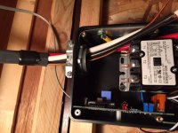
OUTPUT
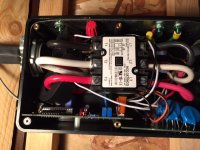
I installed the monitor inside the cabinet with the other control switches and tank monitor
I first looked at the main electrical wiring going into the rig. My Big Horn has a power real. Would not want to be with out it, but an inspection is mandated of you do not want to potentially destroy all the electronics in it or create an electrical fire. Note if you don”t have a power reel, you need to inspect the connections on the back of the RV power connector. It too can have loose connections and cause the same to happen. A loose neutral in the power reel seems to crop up over time. Shake and vibe loosens screws and nuts. To inspect the power connections unplug your electrical cord and pull all of it out of the reel box. This will expose the screws that hold the access panel on. On screw and open the panel. It is spring loaded so when putting it back on, don’t tighten the screws up until all of them have been started.
At first glance it looked good, but when I pushed on the white neutral connections it was very loose. In fact it rattled when moved up and down. The red hot was easy to move, but was sort of almost tight. The rest were tight and would not budge at all. I tightened the loose nuts. Be careful since the threaded studs and nuts are brass. I then applied Loctite between the nut and the stud threads after tightening. Do not use Loctite under the threads here since you do not want to isolate the good mechanical/electrical connection. (I know the pictures are upside down, but I have not figured out how to rotate them.
I took the picture when the Loctite was wet so it would show up in the picture. Do not use penetrating Loctite or an un-removable type. In the aerospace industry, Cab-o-cil, untreated fumed silica which is mixed with uralane conformal coating, is used to absorb shock and vibrations. It requires a bake-out, so it is not practical here, but RTV silicone will work in this application. Apply it on the sides of the nuts to the base. Do not get it on the stud threads. If you do, it will make it more difficult to remove the nuts if necessary in the future. A silicone release agent would have to be used.
Next I looked at the electrical junction boxes under the slides. Several people reported that the wire nuts had come loose and created an open or high resistance connection. I found only one that was ready to fall off. All others were tight. This is what I did to insure that they don’t. I purchased a self-sealing silicone tape. After it is on for a few days, it will have to be cut off to remove it. There are at least two manufactures of this tape. This is the one I used. It can be purchased at Orchard Supply Hardware, Lowe's and other stores.


I did the junction boxes under each slide the same.
This gave me a chance to look at how the electrical wiring is routed under the slide. Oh boy! I am glad it was the green ground that was exposed. The cable makes a sharp 90 degree turn into the slide wall from underneath. This is what I found.
I looked at what might have caused this. When the slide is in, the cable is inside the under side of the fifth wheel floor. There is a rubber water seal at first glance that should not and could not remove the white RTV silicone and insulation of the cable. I pulled back the rubber seal and it revealed a metal backing that was slightly bent. Not enough to allow the wire and silicone that Heartland put on to clear it. On the way in it would just rub, but on the way out it is a sharp cutting edge that grabbed and cut the silicone and cord insulation.
I bent the metal enough to clear the cord and new insulation.
The cord was wrapped with the self-sealing waterproofing tape I used to secure the wire nuts. Then I cover all of it with white silicone RTV.
I have been using and will continue to use an external Sure Guard Protector, but added an internal Progressive Industries 50 Amp surge, voltage, and open neutral protector. On my Big Horn 3010RE, there was not any room to mount it on the floor of the basement. The studs were perfectly spaced to allow it to be mounted between them. This would make the cable too short so I ordered wire from Home Depot and shrink sleeving from DigiKey Electronics. I used strain reliefs on the input cable as well as the new output cable screwed into the studs. If you notice the input cable is six gauge wire, and the output cable is four gauge wire. Electrical code requires 4 gauge wire for 50 amps in electrical building wire applications. In box unit/appliance wiring, the code calls out 6 gauge wire. I guess RV manufactures believe the RV’s are box/appliances. So you could use 6 gauge. The cost difference is small.
INPUT

Used the same silicone tape to build up the insulation for the strain relief.


OUTPUT

I installed the monitor inside the cabinet with the other control switches and tank monitor

