Mini Circuit Breaker Layout on Landmark San Antonio

David-and-Cheryl

Well-known member
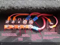
As I was starting to troubleshoot an intermittent Level-Up/slide-out problem, suspecting a weak breaker, I noticed what looks like some odd wiring on the bank of mini circuit breakers. This is in a 2013 Landmark San Antonio.

IMG_5462.jpg

Can anyone tell me what accessories each of these breakers powers? I looked at the 12v block wiring diagram in the User Guides, as well as some other posts, but couldn't find a diagram showing this this particular layout.

I'm also puzzled by three things:

  1. The jumper wire between the fourth and fifth breakers. What is that for?
  2. The manual reset breaker, rightmost on the bus bar, has nothing connected to the top of it, which seems odd.
  3. There are three heavy gauge wires at the top--I assume one to the hydraulic pump and one to the converter, but I don't know what the third is for.

I figured that before I delved into disconnecting things and trying to figure out what does what, I'd ask if anyone else had already deciphered this.
 

danemayer

Well-known member
Can't tell you exactly, but that looks like it's been modified after leaving the factory. The wire on the bottom right probably goes to the cutoff switch and then to the positive terminal on the battery.

Normally the wire to the power converter/fuse box is attached to the top of the breaker where the battery comes in. In yours, it appears that that the wire to the power converter/fuse box has been moved to a different breaker and jumpered to the breaker that probably handles the hydraulic pump.

Hard to say what's going on with the jumper - maybe someone's attempt to fix the intermittent slide problem.

Do you have any devices installed locally rather than at the factory? Solar panels? Sockets for 12V power? Locally added generator?

- - - Updated - - -

Can't tell you exactly, but that looks like it's been modified after leaving the factory. The wire on the bottom right probably goes to the cutoff switch and then to the positive terminal on the battery.

Normally the wire to the power converter/fuse box is attached to the top of the breaker where the battery comes in. In yours, it appears that that the wire to the power converter/fuse box has been moved to a different breaker and jumpered to the breaker that probably handles the hydraulic pump.

Hard to say what's going on with the jumper - maybe someone's attempt to fix the intermittent slide problem.

Do you have any devices installed locally rather than at the factory? Solar panels? Sockets for 12V power? Locally added generator?
 

David-and-Cheryl

Well-known member
Can't tell you exactly, but that looks like it's been modified after leaving the factory. The wire on the bottom right probably goes to the cutoff switch and then to the positive terminal on the battery.

Normally the wire to the power converter/fuse box is attached to the top of the breaker where the battery comes in. In yours, it appears that that the wire to the power converter/fuse box has been moved to a different breaker and jumpered to the breaker that probably handles the hydraulic pump.

Hard to say what's going on with the jumper - maybe someone's attempt to fix the intermittent slide problem.

Do you have any devices installed locally rather than at the factory? Solar panels? Sockets for 12V power? Locally added generator?

Thanks, Dan. I too am thinking that someone has done some modifications to it. We are the second owner, so it could be from before we bought the rig. Or, it's possible that the shop that told me they replaced a breaker three years ago actually just jumpered two others together.

Our generator is factory-installed. The only major 12V accessories we've added is a solar power system, done by Brian Boone, but I don't think he touched these breakers. He added new ones near the solar controller where needed.

I'll go play detective and see if I can figure out what's what.
 

richheck

Seasoned Member
David, here’s a picture of the newer Landmarks layout that Dan posted awhile back to help you get yours back in order. I replaced my self setting breaker to the level ups with a Bussman manual reset 80amp as advised by the manufacture awhile back. My layout is now different being I had to swap positions of the pump breaker and the mini reset to accommodate the larger 80 amp one.

9E9D320A-95B1-49BA-A26A-CB23B2160379.jpg
 

David-and-Cheryl

Well-known member
David, here’s a picture of the newer Landmarks layout that Dan posted awhile back to help you get yours back in order. I replaced my self setting breaker to the level ups with a Bussman manual reset 80amp as advised by the manufacture awhile back. My layout is now different being I had to swap positions of the pump breaker and the mini reset to accommodate the larger 80 amp one.
Thanks Richard. I had looked at that photo, but I seem to have several more accessories on my bus bar than that photo shows.

I've asked Heartland Customer Service to try to dig up the engineering drawing for the 2013 Landmarks and send it to me. Once I get it figured out, either with their help or on my own, I'll try to post an annotated photo for future reference.
 

LBR

Well-known member
I'll make my ASSumption on what happened...

Previous owner had the #6 Main CB either kick out and didn't know about a reset button on it, or the CB just gave up the ghost...so he/she had a loss of 12V charging and supply. Then they tilted top of #6 to the right for clearance and installed main feed wire onto #5 CB to bypass #6. The jumper was to share #4&#5 CB for the modification.

If it were mine, I would do some testing first....but take the jumper from #4&#5 and throw away. Straighten top wire on #4 to get it farther away from CB #5. Take that wire that is now under the jumper on top lug of #5 and put it on top of #6. Leave the back wire on top of #5.

That looks like it would be back to factory configuration to me.

Now, chances are great that #6 CB would need to be reset or replaced.
 

danemayer

Well-known member
Do you know where the output of the solar control connects to the battery? Is it possible the third thick wire is from the solar controller.

I'd hazard a guess that someone installed the jumper on the theory that they could increase current flow by using two breakers in parallel - possibly an attempt to fix the hydraulic pump starting and stopping.

If you haven't read it, take a look at the Hydraulic Slide Out Starts and Stops user guide.
 

David-and-Cheryl

Well-known member
I'll make my ASSumption on what happened...

Previous owner had the #6 Main CB either kick out and didn't know about a reset button on it, or the CB just gave up the ghost...so he/she had a loss of 12V charging and supply. Then they tilted top of #6 to the right for clearance and installed main feed wire onto #5 CB to bypass #6. The jumper was to share #4&#5 CB for the modification.

If it were mine, I would do some testing first....but take the jumper from #4&#5 and throw away. Straighten top wire on #4 to get it farther away from CB #5. Take that wire that is now under the jumper on top lug of #5 and put it on top of #6. Leave the back wire on top of #5.

That looks like it would be back to factory configuration to me.

Now, chances are great that #6 CB would need to be reset or replaced.
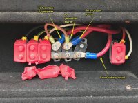
LBR, you hit the nail on the head. The manual reset breaker (#6) had been tripped, and I reset it. That's probably why someone had moved the wires around. Here's what all the original 6 AWG wires were (this is my original photo, just annotated):
IMG_5462 (1).jpg
The extra 6 AWG wire turned out to be the generator starter. So the fuse box/converter, hydraulic pump and generator starter were all sharing a pair of breakers wired in parallel (total 80A or 100A).

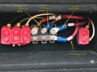
And here's the buss bar after I moved things to what I think are their proper places:
IMG_5463.jpg
The type III (manual reset) breaker (#6) was passing current once I reset it. It may be weak, but I won't know for sure until when and if it fails. Although the wire to that breaker is labeled Fuse Box/Converter, in reality the converter is not connected, because we replaced it with a separately-fused inverter/charger when we put in our solar power system. For now at least, the breaker is working properly.

I also found that the crimp on the line to the fuse box/converter was loose, which might explain some of the problems I'd seen with loss of 12V power to the fuse box at times. I re-crimped it.

I've ordered an 80A breaker to replace the 50A now in use for the hydraulic pump. I've also ordered a 50A type III breaker and a 50A type I (auto reset) breaker to keep as spares in case one of the existing breakers fails, which I almost expect to happen.

Thanks everyone for your help!

- - - Updated - - -

Do you know where the output of the solar control connects to the battery? Is it possible the third thick wire is from the solar controller.

I'd hazard a guess that someone installed the jumper on the theory that they could increase current flow by using two breakers in parallel - possibly an attempt to fix the hydraulic pump starting and stopping.

If you haven't read it, take a look at the Hydraulic Slide Out Starts and Stops user guide.
Dan, the solar controller output is connected directly to the battery bank through a separate fuse installed near the controller. The third 6 gauge wire turned out to be the generator starter circuit.

And thanks for the pointer to that user guide. I read it when I started researching the problem in the first place, and that's how I ended up trying to untangle all the wires on the buss bar so I could figure out which breaker to replace. :)

I have a feeling that the shop that "fixed" our hydraulic slide out stopping problem shortly after we got our rig--before I knew any better--was responsible for the rewiring and jumper mess. They told me they repaired a weak breaker, and I assumed that meant they'd replaced it, not just wired around it. But I guess not.

- - - Updated - - -

One last question: should the breaker on the generator start circuit be 50A or 30A? I'm guessing 50A based on the size of the wire.
 
Top