OldSlowHans
CinC of Everything Else
(Disclaimer --- this is an amateur Do-It-Yourownself project. Proceed at your own risk.)
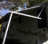
My Big Country has an electric awning. The design is not very robust, and a passing gust of wind can cause all sorts of havoc because the awning tube basically just "floats" out there on the end of the arms. Wanting more stability, like the old familiar "triangle" strut design of manual awnings, I devised an "upper arm" using salvage aluminum tubing from amateur radio antenna projects.
(In the instructions below, click on each image for a better size view)
Each arm assembly (one a each end of the awning) consists of two aluminum tubes which "telescope" inside each other.
The inner tube is 4-feet long, ¾” OD, and the outer tube is 6-feet long, 7/8” ID. These telescope together nicely, not “snug” but not much play.
Other material needed:
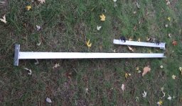
This first photo shows the two tubes laying on the ground. The top one is a complete tube, and the bottom shows the inner section and the outer section separated.
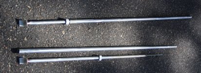
The outer tube is just a 6-foot section of tube, with a ¼” hole drilled all the way through, ½” from one end. (You will see other holes in mine, these are holes that were already in my salvaged material).
The inner section of tubing is an assembly made as follows.
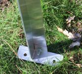
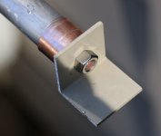
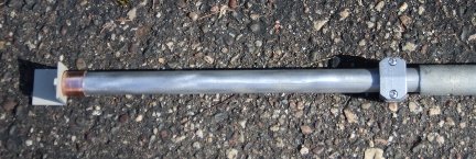
The photos below shows how that will look when finished. The end of that L-bracket will fit into the canvas slot on the awning roller.
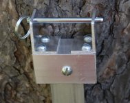
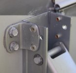
On the trailer, at the top of the vertical channel, drill a ¼” hole all the way through both sides of the channel, as shown below.
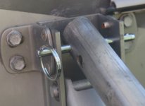
Using a ¼” x 3” pin, attach the assembly to the trailer.
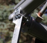
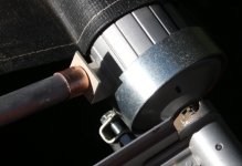
Extend the lower tube out and insert the L-bracket into the awning roller into the slot at the end of the canvas.
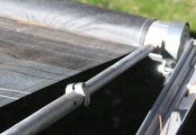
Extend the lower section until it is taut, then secure it in place with a hose clamp.
Repeat at other end of the awning.
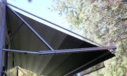
Sit back, admire your work, and have a beer.
PS: This also provides an attachment point for those old "deflappers" from your last rig, which wouldn't normally work with your newfangled flimsy electric awning.
My Big Country has an electric awning. The design is not very robust, and a passing gust of wind can cause all sorts of havoc because the awning tube basically just "floats" out there on the end of the arms. Wanting more stability, like the old familiar "triangle" strut design of manual awnings, I devised an "upper arm" using salvage aluminum tubing from amateur radio antenna projects.
(In the instructions below, click on each image for a better size view)
Each arm assembly (one a each end of the awning) consists of two aluminum tubes which "telescope" inside each other.
The inner tube is 4-feet long, ¾” OD, and the outer tube is 6-feet long, 7/8” ID. These telescope together nicely, not “snug” but not much play.
Other material needed:
- Two ¾” copper caps used for capping off ¾” copper plumbing pipe.
- Two 5/16” threaded rod 4.5 feet long.
- Two aluminum “L” brackets, 1”x1”. (I cut mine off the end of a piece of aluminum angle bracket)
- Two hose clamps, stolen from a garden hose repair kit.
- Various nuts and washers.
This first photo shows the two tubes laying on the ground. The top one is a complete tube, and the bottom shows the inner section and the outer section separated.

The outer tube is just a 6-foot section of tube, with a ¼” hole drilled all the way through, ½” from one end. (You will see other holes in mine, these are holes that were already in my salvaged material).
The inner section of tubing is an assembly made as follows.
- Drill a 5/16” hole in the end of the copper pipe caps.
- Drill a 5/16” hole in one side of each of the L-brackets
- Using 2 nuts, attach an L-bracket and a pipe cap to one end of each threaded rod.
- Insert the other end of the threaded rod into the ¾” aluminum tube.
- Tap the copper cap over the end of the tube until it bottoms out.
- At the other end of the threaded rod I put a washer between 2 nuts so the rod wouldn’t flop around in there. Slide the two sections together.
The photos below shows how that will look when finished. The end of that L-bracket will fit into the canvas slot on the awning roller.


On the trailer, at the top of the vertical channel, drill a ¼” hole all the way through both sides of the channel, as shown below.

Using a ¼” x 3” pin, attach the assembly to the trailer.

Extend the lower tube out and insert the L-bracket into the awning roller into the slot at the end of the canvas.

Extend the lower section until it is taut, then secure it in place with a hose clamp.

Repeat at other end of the awning.

Sit back, admire your work, and have a beer.
PS: This also provides an attachment point for those old "deflappers" from your last rig, which wouldn't normally work with your newfangled flimsy electric awning.

