dmholmgren
Member
We just bought a Sundance 3700RLB. It is our first RV and we wanted the 2 bedroom 2 bathroom layout because we have a 7 and 9 year old. It was between a Forest River with OneControl and ours that didn’t have it. We went with the Sundance because it had the Ground Control 3.0 installed. The other didn't. I'm into home automation, so I've been looking to retrofit the touchscreen control. Its easier to retrofit the electronics than retrofitting the retrofitting the Ground Control. I didn't want to go more expensive on the trailer because I wasn't sure how much we were actually going to use it (which is apparently a lot-- it was a hit with the wife and kids).
The available OneControl components are listed here:
https://manuals.heartlandowners.org/...Components.pdfThe available OneControl components are listed here:
In addition, there is a tank monitor module that can be found on the web.
A good thread on the subject is here:
https://www.jaycoowners.com/forums/f...rol-60764.htmlA good thread on the subject is here:
I was curious and started buying stuff off of eBay. For a test platform, I got a 5" touch panel (406345) along with a couple of 8 function receivers (344923). Here is what I have learned from the limited information available on the internet and from playing around with the toys I got off of eBay.
The touch panel will power on from a normal USB charger with a USB Mini B cable. It runs a Lippert modified version of Android. It comes with the manuals and instructions for the full line of components available in the OneControl product line regardless of what is (or is not) connected to it. It is part of the base software. For those with the new version of Ground Control, the touch screen talks with the leveling controller using CAN bus, which is an industry standard promulgated by RIVA.
https://www.rvia.org/standards-regul...pliance/rv-ctmThe touch panel will power on from a normal USB charger with a USB Mini B cable. It runs a Lippert modified version of Android. It comes with the manuals and instructions for the full line of components available in the OneControl product line regardless of what is (or is not) connected to it. It is part of the base software. For those with the new version of Ground Control, the touch screen talks with the leveling controller using CAN bus, which is an industry standard promulgated by RIVA.
http://www.rv-c.com/To control slides and other components, one of the receivers is needed. Look on page 3 of the components manual. Each of the components daisy chains with the other components using the "Canbus data harness" cables. Although that is a fancy name, the CANBUS cables are basically unshielded twisted pair wires with Molex ends. If you don't want to buy the cables from Lippert, the Molex part number is 39-01-2020. Amazon sells them:
https://www.amazon.com/gp/product/B0...?ie=UTF8&psc=1
Although they are “crimp” I recommend soldering.
I have not managed to find the ends for the power leads. I need to spend some more time on
DigiKey, Molex, and Mouser. Either that, or I will try and buy them from Lippert.
I got the components hooked up on a test bed and powered them up using a 12 volt power supply.
The slides and awnings are controlled by the receivers.
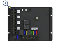
Here it is hooked up on my desk. The function relays are on the left, oriented vertically. They are reversing relays. The horizontal connectors at the bottom are switch power feeds so that the system can be installed in parallel with the physical switches. For orientation, here is Lippert's standard slide diagram.
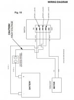
The slides go in and out based on the polarity of the power feed to the motor. For this example, I used two (2) way LEDs on the reversing relays. Polarity in one direction makes the LED light green, the other red. With no function active, the switch connections have +12 volts and no current flows between the function connections.
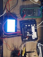
When slide retract is activated on the touch panel, the switch current drops to 0 volts and the LED lights red.
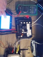
When slide extend is active, the LED lights red and no power is supplied to the switch leads.
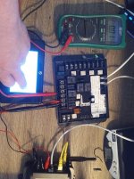
I haven't yet removed the wall in the basement to see if I have slide controllers, but, assuming I don't, the power to the physical switches will be suppled from the bottom of the receiver. The leads to the slide motor will be connected in parallel on the left hand side of the board. With no function active, each physical switch will get power from the receiver and work the slide. With a function active, power to the switches are cut so there is no possibility of shorting they system out. It is all relay controlled, so there is physical isolation.
One of the biggest complaints I have seen with this system is that, in most factory implementations, the OneControl system is the only control, which is a shame because it is designed to operate in parallel with physical switches. If one of the CANBUS cables comes loose, most people are screwed. Even at the house, from a design perspective, I generally prefer automation to be an overlay rather than the primary control. For example, I use Lutron's RadioRA2 system for lighting. If the main receiver fails or otherwise goes on the blink, I still have physical light switches to handle each load. Alexa may not turn the kitchen on or off, but I can still get off my butt and press the switch on the wall. I am still trying to get my hands on a OneControl lighting controller to figure out how I can overlay that onto physical switches using three way physical switches and relays.
Programming is easy. The switch functions are defined in the Android touch panel. To send to the control, select sync and push the button on the receiver to sync. Once the receiver is programmed, any new touch panels and devices connected to the Wi-Fi gateway see the configured receiver and the functions automatically appear. Interestingly, the older school wireless touch pad will talk with the receiver and Ground Control. https://www.amazon.com/gp/product/B00S2IALQU/ref=oh_aui_search_detailpage?ie=UTF8&psc=1 It looks like Lippert overlaid CANBUS onto the older receivers and left the original wireless functions in tact.
The system has a Wi-Fi gateway available. T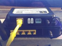
I got the components hooked up on a test bed and powered them up using a 12 volt power supply.
To make it work, a terminating resistor is needed. Without the terminating resistor, the components won't talk with each other. According to the standard, it needs one (1) on each end. On my test bed, I only used one (1) and it worked fine. I will use two (2) when I install it.
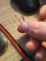
Once the CAN Bus cables are connected, the bus terminated with a resistor, and everything is powered on, the touchscreen will see what is on the bus automatically. To go into the setup menus, tap the OneControl icon on the top left hand corner of the screen 5 times. From there it is pretty easy if you read the programming guide. https://www.lci1.com/assets/content/support/manuals/Electronics/OneControl_Programming_Manual.pdf You don't need the fancy tablet, you can program it from the touchscreens. You can buy Lippert's or go to Fry's or another electronics store and get a couple of 120 ohm resistors and solder them to the Molex pins,
I know this isn't pretty, but it is my test bed. Everything will be nicer when I install it next weekend.
cover it with some heat shrink tubing, and shove the pins in the Molex connectors.

I know this isn't pretty, but it is my test bed. Everything will be nicer when I install it next weekend.
The slides and awnings are controlled by the receivers.

Here it is hooked up on my desk. The function relays are on the left, oriented vertically. They are reversing relays. The horizontal connectors at the bottom are switch power feeds so that the system can be installed in parallel with the physical switches. For orientation, here is Lippert's standard slide diagram.

The slides go in and out based on the polarity of the power feed to the motor. For this example, I used two (2) way LEDs on the reversing relays. Polarity in one direction makes the LED light green, the other red. With no function active, the switch connections have +12 volts and no current flows between the function connections.

When slide retract is activated on the touch panel, the switch current drops to 0 volts and the LED lights red.

When slide extend is active, the LED lights red and no power is supplied to the switch leads.

I haven't yet removed the wall in the basement to see if I have slide controllers, but, assuming I don't, the power to the physical switches will be suppled from the bottom of the receiver. The leads to the slide motor will be connected in parallel on the left hand side of the board. With no function active, each physical switch will get power from the receiver and work the slide. With a function active, power to the switches are cut so there is no possibility of shorting they system out. It is all relay controlled, so there is physical isolation.
One of the biggest complaints I have seen with this system is that, in most factory implementations, the OneControl system is the only control, which is a shame because it is designed to operate in parallel with physical switches. If one of the CANBUS cables comes loose, most people are screwed. Even at the house, from a design perspective, I generally prefer automation to be an overlay rather than the primary control. For example, I use Lutron's RadioRA2 system for lighting. If the main receiver fails or otherwise goes on the blink, I still have physical light switches to handle each load. Alexa may not turn the kitchen on or off, but I can still get off my butt and press the switch on the wall. I am still trying to get my hands on a OneControl lighting controller to figure out how I can overlay that onto physical switches using three way physical switches and relays.
Programming is easy. The switch functions are defined in the Android touch panel. To send to the control, select sync and push the button on the receiver to sync. Once the receiver is programmed, any new touch panels and devices connected to the Wi-Fi gateway see the configured receiver and the functions automatically appear. Interestingly, the older school wireless touch pad will talk with the receiver and Ground Control. https://www.amazon.com/gp/product/B00S2IALQU/ref=oh_aui_search_detailpage?ie=UTF8&psc=1 It looks like Lippert overlaid CANBUS onto the older receivers and left the original wireless functions in tact.
The system has a Wi-Fi gateway available. T
he gateway is a CANBUS to Ethernet bridge piggybacked onto an inexpensive Wi-Fi router. I plan on ditching the router part and hooking it directly to my MoFi.
http://mofinetwork.com/ The bridge is set to DHCP, so it should work and pull an IP address on the RV network. I will play with it on my home network to verify.
Here is a picture of the connections on the gateway.
Here is a picture of the connections on the gateway.

The top box is the Lippert CANBUS to Ethernet bridge. The bottom box is the generic router. The two (2) vertical white connectors are the CANBUS connectors. The one next to it is for power. Once it is hooked up, the touch panels see it and you can control configured items from iOS and Android devices. You can't program the system from these devices, so you will need a Lippert touch panel. I found a few for $90 on eBay.
Now that I have it working at my house, it is time to install it on the RV.
Now that I have it working at my house, it is time to install it on the RV.
