explorer2316
Explorer2316
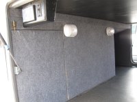
2015 Landmark Newport - Cargo Bay Project - Part 2 Part one was the front wall of the cargo bay. I thought that part one was a tough and time consuming project that required a lot of sitting back and thinking about how to best lay out the new walls. Little did I know it would be nothing compared to Part 2. If you read Part 1 the project idea was born when I had to remove the front cargo bay wall section to access a black tank sprayer line. When the wall was removed I found there was some additional floor space that could be captured if the wall was modified. I also didn't like the fact the wall was screwed into the floor and figured there has to be a better way to skin that cat than keep making new holes each time the wall was removed. If the design is done properly there is no need to screw any of the barriers to the ceiling or floor. The “C” channel and aluminum top stops were again used to keep the barrier securely in place.
This is the before picture.
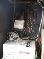
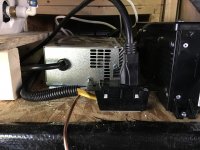
After removing the existing walls, there were a number of items that required relocation to one degree or another. After all of them were addressed the NEW wall location could be determined. The first was the 120 receptacle. Its location caused the cord that was plugged in to stick way out and require relocation. Before and after pictures below. Note: The inverter was mounted so the cooling fins were touching the surge suppressor and impacting air movement over the fins. The inverter was moved about 2” to the left to allow good air flow.
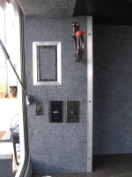
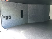
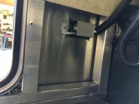
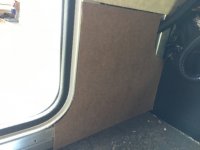
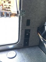
The next step was to find a new location for the TV jack, 120 receptacle, and cargo bay light switch. I removed a panel on the inside of the outside wall that had been exposed after removing the existing wall. A new piece of 1/8” board was cut to fit the area for mounting the devices. Note: The opening where the existing receptacle power was routed is large enough for the additional wiring to be added. This wiring will be behind the new wall location. The existing wall and new piece were covered with the new material and items mounted.
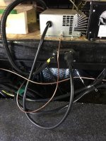
By the water heater, there was a large bundle of wires that were sticking way out. The Ty-Raps were removed and the bundle flattened out. The wires were then secured again.
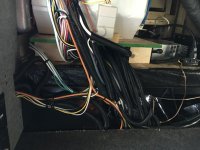
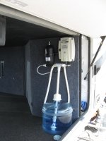
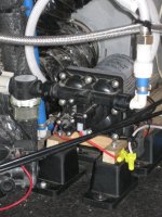
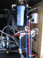
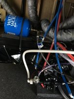
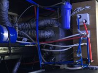
The next area that required some work was over by the pump and plumbing. You may note that I had done a previous project to mount the pump on high density foam and install a water expansion tank. If you do any dry camping this is something you definitely want to do. The foam quiets the pump noise down dramatically, and the expansion tank stops continuous “Rrrr, Rrrrr, Rrrr” of the pump. Make sure to use flexible lines on the pump in and out, and get rid of the PEX connections. Getting back on the project track, the pump needed to be relocated up to the upper level next to the expansion tank. The water filter on the ceiling had to be moved about 6” closer to the Utility cabinet. Also, I cut some new pieces of PEX pipe, crimped new connections, and Ty-Raped the pipes to clean up the factory’s plumbing explosion. See the before and after below.
Next was to lay out the wall locations and install the aluminum “C” channel on the floor and other supports.
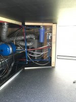
Then I started making and putting the walls in. The first piece was next to the Utility cabinet. A 1/8” piece ply was cut, fitted, and covered. The lip on the side of the Utility cabinet was 1/8”, so the new piece was perfect and flush with the trim.
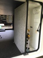
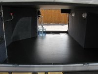
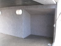
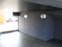
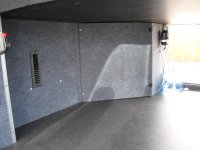
The other two pieces were cut and covered, and the ventilation louver installed. PROJECT COMPLETE!
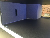
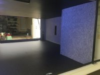
Front side from Part 1
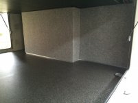
At the end of the day, I took some measurements. The original cargo area was approximately 96 cubic feet in size. The new cargo area is 123.5 cubic feet. Simple math seems to indicate that I increased by cargo area by 27.5 cubic feet. That is a 28.6% increase in storage area. I personally feel it was worth the work. It not only increased my storage area but I got to really get familiar with what’s in the belly of the beast.
This is the before picture.

After removing the existing walls, there were a number of items that required relocation to one degree or another. After all of them were addressed the NEW wall location could be determined. The first was the 120 receptacle. Its location caused the cord that was plugged in to stick way out and require relocation. Before and after pictures below. Note: The inverter was mounted so the cooling fins were touching the surge suppressor and impacting air movement over the fins. The inverter was moved about 2” to the left to allow good air flow.


The next step was to find a new location for the TV jack, 120 receptacle, and cargo bay light switch. I removed a panel on the inside of the outside wall that had been exposed after removing the existing wall. A new piece of 1/8” board was cut to fit the area for mounting the devices. Note: The opening where the existing receptacle power was routed is large enough for the additional wiring to be added. This wiring will be behind the new wall location. The existing wall and new piece were covered with the new material and items mounted.


By the water heater, there was a large bundle of wires that were sticking way out. The Ty-Raps were removed and the bundle flattened out. The wires were then secured again.

The next area that required some work was over by the pump and plumbing. You may note that I had done a previous project to mount the pump on high density foam and install a water expansion tank. If you do any dry camping this is something you definitely want to do. The foam quiets the pump noise down dramatically, and the expansion tank stops continuous “Rrrr, Rrrrr, Rrrr” of the pump. Make sure to use flexible lines on the pump in and out, and get rid of the PEX connections. Getting back on the project track, the pump needed to be relocated up to the upper level next to the expansion tank. The water filter on the ceiling had to be moved about 6” closer to the Utility cabinet. Also, I cut some new pieces of PEX pipe, crimped new connections, and Ty-Raped the pipes to clean up the factory’s plumbing explosion. See the before and after below.


Next was to lay out the wall locations and install the aluminum “C” channel on the floor and other supports.

Then I started making and putting the walls in. The first piece was next to the Utility cabinet. A 1/8” piece ply was cut, fitted, and covered. The lip on the side of the Utility cabinet was 1/8”, so the new piece was perfect and flush with the trim.

The other two pieces were cut and covered, and the ventilation louver installed. PROJECT COMPLETE!


Front side from Part 1

At the end of the day, I took some measurements. The original cargo area was approximately 96 cubic feet in size. The new cargo area is 123.5 cubic feet. Simple math seems to indicate that I increased by cargo area by 27.5 cubic feet. That is a 28.6% increase in storage area. I personally feel it was worth the work. It not only increased my storage area but I got to really get familiar with what’s in the belly of the beast.

