Breaker between battery and cut-off switch

Oregon_Camper

Well-known member
Anyone know why there is a 50amp breaker between the battery and the factory installed cut-off switch? I've had a few times recently, where the LCI panel cuts out for ~10 seconds, when raising/lowering the landing gear. The LCI panels flashes...goes dark for ~10 seconds...then comes back to life.

Shown below is part of my wiring diagram (yea, I know I'm a bit over the top on creating diagrams :cool:) with a blue arrow where this 50amp fuse is located.
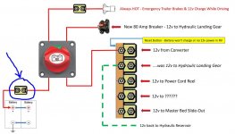
Capture.jpg
 

RDsStudio59

Well-known member
Anyone know why there is a 50amp breaker between the battery and the factory installed cut-off switch? I've had a few times recently, where the LCI panel cuts out for ~10 seconds, when raising/lowering the landing gear. The LCI panels flashes...goes dark for ~10 seconds...then comes back to life.

Shown below is part of my wiring diagram (yea, I know I'm a bit over the top on creating diagrams :cool:) with a blue arrow where this 50amp fuse is located.

View attachment 55300
Beautiful diagram. Probably because it is a 50 amp circuit? Why is there a "New 80 amp breaker" in the leveling/landing gear circuit?

Safe Travels,

Roger
 

danemayer

Well-known member
Jim,

I'm not sure the emergency brake circuit and connection to the tow vehicle power are wired together from the factory, both going through the same circuit breaker as shown in your diagram. I think the breakaway circuit normally goes through a breaker. The extra 50 amp breaker might be to protect against a problem in the tow vehicle connection.
 

Oregon_Camper

Well-known member
I'm not sure the emergency brake circuit and connection to the tow vehicle power are wired together from the factory, both going through the same circuit breaker as shown in your diagram. I think the breakaway circuit normally goes through a breaker. The extra 50 amp breaker might be to protect against a problem in the tow vehicle connection.

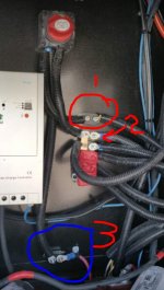
Dan...the image below is how my system was setup from factory, except for the MPPT controller for solar.

#1 - is the factory emergency brake line. That was left intact...not moved or rewired. (however in my wiring diagram I make it look different/cleaner)

#2 - Original Hydraulic power line. That was removed from busbar and now has its own 80amp breaker.

#3 - This is the breaker in question. I see no need for it. Everything else is already on a breaker.

BTW...if you thought I wired the Emergency Brake and the Tow Vehicle power together as they enter the cut-off...they are not. The Emergency Break is on the "always powered" side (not off when cut-off is off). The TV power is on the other side and IS off if the switch is off.

Capture.jpg
 

6.7LMegaCab

Well-known member
The breaker would be there for protection, although in your setup, I don't know that it is entirely necessary. However, every device downstream of the switch will get no more than 50 amps because that breaker will not allow it. That 80 amp is doing nothing because that 50 amp will go first. It's not an entirely bad setup as it is providing protection directly from the battery. If this was my rig, I'd tally up the required amps for all components running directly off the battery and replace the 50 amp battery breaker with an appropriately sized breaker. The screen is more than likely blanking because the 50 amp breaker is being over drawn by the hydraulic system (the 80 amp breaker is literally doing nothing for it, since again it's limited by the 50 amp breaker). Does the hydraulic system really need 80 amps (I'm assuming that is 2x 40 amp breakers)? Try putting the 80 amp breaker setup in place of the 50 amp and vice versa. I bet your panel problems go away and your hydraulic system may perform better than a single 40 amp breaker. I personally would keep a breaker there, it just needs to be as big as the 80 amp.

Sent from my SM-G920V using Tapatalk
 

SNOKING

Well-known member
If you do not mine, I also have a 12V question. We are getting ready to store our 2017 for the winter here in Arizona. I noticed a White/Black 12 gauge(?) set of wires leaving a direct connection to my batteries and going up into the over head of the front storage area above the hydraulic pump. If these are going to the little charge plug near the landing gear switch, I do not understand why they would go into the overhead. Anyone have an idea what these wires are for?

Chris
 

danemayer

Well-known member
Dan...the image below is how my system was setup from factory, except for the MPPT controller for solar.

#1 - is the factory emergency brake line. That was left intact...not moved or rewired. (however in my wiring diagram I make it look different/cleaner)

#2 - Original Hydraulic power line. That was removed from busbar and now has its own 80amp breaker.

#3 - This is the breaker in question. I see no need for it. Everything else is already on a breaker.

BTW...if you thought I wired the Emergency Brake and the Tow Vehicle power together as they enter the cut-off...they are not. The Emergency Break is on the "always powered" side (not off when cut-off is off). The TV power is on the other side and IS off if the switch is off.

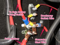
Here's a notated photo from a LM365. Notice that the wire from the battery goes to a breaker connected by buss bar to another breakers. One breaker feeds the line to the cutoff switch. The other to the breakaway switch.

Also notice the generator start cable is after the 1st breaker. The first breaker is protecting the battery from a short on the generator start wiring. The 2nd breaker appears to be protecting the downstream connections that are after the cutoff switch, although that one might be redundant.

With respect to the hydraulics tripping a breaker, it could be any of these, as well as the one on the main buss bar.

breakaway switch buss bar closeup notated.jpg
 

G_S

Well-known member
Beautiful diagram. Probably because it is a 50 amp circuit? Why is there a "New 80 amp breaker" in the leveling/landing gear circuit?

Safe Travels,

Roger

Ours was tripping the 50 amp breaker causing the landing gears and living area slides not to work. We were told the system was upgraded to the 80 amp on newer models so we got the upgrade. I am not sure why we were not notified prior to our having to deal with the problem.


Sent from my iPhone using Tapatalk
 

RDsStudio59

Well-known member
Ours was tripping the 50 amp breaker causing the landing gears and living area slides not to work. We were told the system was upgraded to the 80 amp on newer models so we got the upgrade. I am not sure why we were not notified prior to our having to deal with the problem.


Sent from my iPhone using Tapatalk
When I had a problem with my landing gear and slides tripping the 50 amp breaker my dealer wanted to do the same thing. I called Heartland and they told me that was not an authorized repair in 2016 as the circuit wiring was only rated for 50 amps.
As stated already the 80 amp breaker is reduced to 50 amp as wired anyway.
The 80 amp breaker only covers up the real problem.

Safe Travels,

Roger
 

RDsStudio59

Well-known member
You should put an amp clamp and meter on the cable to the pump and monitor it while running. Mine was drawing 142 amps in one direction if I remember correctly.
After the proper repair it was drawing 38 to 43 amps on a 50 amp breaker and has worked correctly ever since.

Safe Travels,

Roger
 

BighornELK

Active Member
You should put an amp clamp and meter on the cable to the pump and monitor it while running. Mine was drawing 142 amps in one direction if I remember correctly.
After the proper repair it was drawing 38 to 43 amps on a 50 amp breaker and has worked correctly ever since.

Safe Travels,

Roger

What was the proper repair?
 

RDsStudio59

Well-known member
What was the proper repair?
After much time diagnosing the Heartland Service Center in Elkhart advised me they found two hoses reversed in connection.
I inspected the system after I picked it up and couldn't tell which ones were involved. I can tell you my system still works well and is on a 50 amp breaker.
Might be worth a call to Heartland CS at 8772628032 have your VIN ready

Safe Travels,

Roger
 

PondSkum

Well-known member
In 12v systems, it's customary to have a fuse or breaker in the main line, close to the battery, before all other accessories (including fuse boxes, breaker buss bars, etc.). This fuse or breaker should have an amperage rating capable of withstanding the current drawn from all the connected accessories. As a few have stated above, the 80A breaker after the 50A breaker is not doing anything.
 
Last edited:

Jesstruckn/Jesstalkn

Well-known member
If you do not mine, I also have a 12V question. We are getting ready to store our 2017 for the winter here in Arizona. I noticed a White/Black 12 gauge(?) set of wires leaving a direct connection to my batteries and going up into the over head of the front storage area above the hydraulic pump. If these are going to the little charge plug near the landing gear switch, I do not understand why they would go into the overhead. Anyone have an idea what these wires are for?

Chris
Chris, that plug is for a portable solar panel.

Sent from my XT1585 using Tapatalk
 

Jesstruckn/Jesstalkn

Well-known member
In my set up I ran a good heavy duty battery cable from my 12v + bus bar directly to my new 80amp manual reset curuit breaker, to run the hydraulic system. (Sorry some day I'll get Jim to make me a better looking diagram) LOL
My 80amp manual breaker actually tripped last week when I was manually raising my legs. It was when they all hit the top.
c350791d89503a46cdf5fc8812368474.jpg


Sent from my XT1585 using Tapatalk
 

SNOKING

Well-known member
Chris, that plug is for a portable solar panel.

Sent from my XT1585 using Tapatalk

Yes I know that plug is for a external solar panel, however I do not think the wires I was asking about. But on looking again, I could not even fine the wires I was talking about. Getting old sucks!

BTW, our main fuse in the red battery lead is 60 AMPs. This an early build 2017 BH. Chris
 

Jesstruckn/Jesstalkn

Well-known member
Yes I know that plug is for a external solar panel, however I do not think the wires I was asking about. But on looking again, I could not even fine the wires I was talking about. Getting old sucks!

BTW, our main fuse in the red battery lead is 60 AMPs. This an early build 2017 BH. Chris
I guess I miss read your question then. Sorry

Sent from my XT1585 using Tapatalk
 

RDsStudio59

Well-known member
In my set up I ran a good heavy duty battery cable from my 12v + bus bar directly to my new 80amp manual reset curuit breaker, to run the hydraulic system. (Sorry some day I'll get Jim to make me a better looking diagram) LOL
My 80amp manual breaker actually tripped last week when I was manually raising my legs. It was when they all hit the top.
c350791d89503a46cdf5fc8812368474.jpg


Sent from my XT1585 using Tapatalk
Did you replace the cable from your new 80 amp breaker to the pump motor as well? If not you are still running on a 50 amp rated cable.

Safe Travels,

Roger
 
Top