Install of Inverter, EMS and Transfer Switch

Oregon_Camper

Well-known member
I do not turn it off.
Everything works fine


Sorry if my response implied it wouldn't work....as it clearly does.

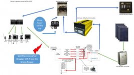
I was just saying if you leave the inverter on (vs quick on/off as needed) then you'll lose power due to the power loop. So, if your dry camping and want to watch a movie on TV off DVD or computer...the system will run everything, but it will also be charging your battery, off inverted power during the 60-90 mins the movie is playing.
 

sjandbj

Well-known member
You must be turning off the Converter...right? Otherwise you'll have an endless loop and you'll be losing power due to converting...inverting over and over and over and over (well, you get the picture) :)

My inverter is also my charger along with my solar. I have my original charger/convertor still installed but the circuit breaker is turned off. It can be turned on if I ever need it. You are correct that it can create a loop if left on depending on the wiring.

Steve
 

porthole

Retired
read instructions for the progressive surge today in preparation of installing mine Thursday- says not to place after inverter-
copied from progressive install instructions:

• Never plug the EMS into an inverter.


The problem with the progressive instructions is they only say not to plug into an inverter. They do not say why.

You can plug it in, and it will work - ONE TIME.

Then the EMS will no longer function.

Go ahead - ask me how I know.

- - - Updated - - -

And should someone not heed the warning or have another reason for the progressive to have failed, here is how you can bypass the Progressive EMS until you get replacement parts.
 

esscobra

Well-known member
so here is updated of how you should wire ems to your setup and also on of how I plan to do it- I plan on removing the circuits I want to run from inverter from oem panel- place into subpanel - fed by transfer 30a transfer switch which is fed by inverter and one open the open breakers where I removed items from oem box

- - - Updated - - -

my plan
 

Attachments

  • updated.jpg
    updated.jpg
    20.2 KB · Views: 46
  • my plan.jpg
    my plan.jpg
    20.2 KB · Views: 40
Last edited:

sjandbj

Well-known member
so here is updated of how you should wire ems to your setup and also on of how I plan to do it- I plan on removing the circuits I want to run from inverter from oem panel- place into subpanel - fed by transfer 30a transfer switch which is fed by inverter and one open the open breakers where I removed items from oem box

- - - Updated - - -

my plan
I did not see a transfer switch in your diagram for the shore or Inverter power. How do you plan on dealing with this. Other than that it looks good.
 

Oregon_Camper

Well-known member
I did not see a transfer switch in your diagram for the shore or Inverter power. How do you plan on dealing with this. Other than that it looks good.


Transfer Switch is there...top/center of image.

- - - Updated - - -

so here is updated of how you should wire ems to your setup and also on of how I plan to do it- I plan on removing the circuits I want to run from inverter from oem panel- place into subpanel - fed by transfer 30a transfer switch which is fed by inverter and one open the open breakers where I removed items from oem box

- - - Updated - - -

my plan


Did you mean to attach an image with the subpanel?

Here is my update diagram, based on the input from this thread....moved the EMS before Transfer Switch.

Capture.jpg
 

Jesstruckn/Jesstalkn

Well-known member
You had me curious of how this was wired.
My convertor is wired directly into the input of the 2nd transfer switch come from the first one.
So when invertor is on convertor is not.
f0be653dfa08e82f545ba8d7f5aa5545.jpg


Also there is a loop from L1 over to L2 so both sides are hot with invertor power.

b1139a2751ed07fb18c8808d4d254179.jpg


83ab884d35f0c774238fb91ece761c57.jpg


a5005d7f4ed1925a9cacfcd598a358f4.jpg


Sent from my XT1585 using Tapatalk
 

Oregon_Camper

Well-known member
You had me curious of how this was wired.
My convertor is wired directly into the input of the 2nd transfer switch come from the first one.
So when invertor is on convertor is not.


Now that is a perfect solution!!! I will wire mine this way as well. Take 110v off either L1 or L2 and wire the plug to that. Then I don't have to worry about remembering to flip the circuit breaker.

Love this place and all the GREAT information!!! I will update my diagram again later tonight, so hopefully it will help someone else down the road.
 

Jesstruckn/Jesstalkn

Well-known member
The only thing I see there that I'm a little scratchy on is that there is no circuit breaker on that plug for the converter.

It has fused for the 12v but nothing on THE 120 side.
You could maybe use a GFI plug there but I don't know if you can get a 20 amp GFI plug.
Next option would be the run the plug through a breaker and add a small accessable box in your wall that you could get to if needed.
As for mine I'm sure it's just fine like that. 😎

Sent from my XT1585 using Tapatalk
 

esscobra

Well-known member
picking up mine tomorrow- I have the factory installed gen prep- so there is transfer switch for gen or shore power- since bighorns do not have the power management systems- I would rather make a sub panel for the items I want to run off inverter- rather than risk guests- sig other- etc accidentally turning on something and overloading the inverter or popping fuse/link- I usually over engineer-/build things to avoid any possible problems failures.
 

Attachments

  • navasota1.jpg
    navasota1.jpg
    97.1 KB · Views: 15
  • navasota2.jpg
    navasota2.jpg
    109.2 KB · Views: 16
Last edited:
Top