You are using an out of date browser. It may not display this or other websites correctly.
You should upgrade or use an alternative browser.
You should upgrade or use an alternative browser.
Planning Electrical Mods
- Thread starter StrongJava
- Start date
StrongJava
Well-known member
Re: Planning Electrical Mods -- Drawings & questions
Hi y'all--
I've developed a plan and have attached my drawing.
I thought I would add a plug in the forward compartment so I could connect my generators and run them from under the nose. Then I thought I'd change GP0 to SP1 (50A) so I would have an option of plugging regular shore power in up there. But I also wanted to add an electrical management system, but haven't figured out a way to hardwire one so it could be used to protect the coach regardless of which connector I used, without putting it downstream of the transfer switch. The Progressive Industries rep I spoke with suggested this would leave the transfer switch vulnerable. One option is to sacrifice it, if that is a real risk? Any ideas?
Additionally, I've been trying to find a simple manual transfer switch. I think the 60A I found at Lowes ($99) is about the cheapest, but am looking for other options that people have implemented.
Cheers, Tim
Attachments
StrongJava
Well-known member
But Dan said you knew all about these things! ")
I made the drawing with AutoDesk Graphic for Mac, a very reasonably priced ($29) and powerful graphics program. The primary limitation is that it doesn't have connectors for the line, so when objects get moved, the lines have to be manually moved/changed.
Tim
I made the drawing with AutoDesk Graphic for Mac, a very reasonably priced ($29) and powerful graphics program. The primary limitation is that it doesn't have connectors for the line, so when objects get moved, the lines have to be manually moved/changed.
Tim
Hi Tim - I can't critique your circuit but I love the dwg!
Side note, before my my call with Emily today, I had not made the connection between her and you (StrongJava). Now I know
But Dan said you knew all about these things!
I made the drawing with AutoDesk Graphic for Mac, a very reasonably priced ($29) and powerful graphics program. The primary limitation is that it doesn't have connectors for the line, so when objects get moved, the lines have to be manually moved/changed.
Tim
I may have to get that program.
When I studied your DWG, I also thought of Dan B. I'll bet you guys got along well there in NV before they left.
Bogie
Well-known member
Hi Tim,
Great Drawing!
It looks like you're mixing 220 volt and 120 Volt. SPO (symbol) is a 220 volt 50 amp service and GP0 (symbol) is a 120 volt 30 amp service. That said, I can't tell exactly what you are planning. Are you going to use a 220 volt inverter and a 220 volt generator?
In your OP, you mentioned you won't be powering everything. If you use a 120 volt inverter and generator, you will have to figure out how to split the loads to power only what you need/want to power.
As I am not completely familiar with the internal wiring of a trailer with 220 volt 50 amp service, I don't know what you will need to do to address this.
Also, don't forget, you have to isolate (disconnect from AC) the converter that charges the batteries when you are using the inverter.
Though not required, I would add isolation switches between the batteries and the 12 volt bus bar and an additional one between the battery and the inverter. But, that's just me.
Finally, I don't know what the Progressive Industries tech meant by "leaving the transfer switch exposed". One thing I can tell you is I have to turn my Progressive Industries power management system to "off" when on generator. The reason for this is a generator does not have a true ground. The PI unit recognizes this and will not turn the power on when on a generator. Since I use a pure sine generator, this does not present a problem for me.
Best
From your drawing it looks like you have 2000w inverter/charger and are planning on entire AC load being from inverter and are running both circuits thru inverter. Does inverter have built in transfer for AC? Can 2000w carry all your ac load? I have a 2000w inveter/charger with built in AC transfer. I have a 30a circuit powering inverter from trailer AC panel and inverter AC to a sub panel with the circuits I want it to power,3 in my case.
StrongJava
Well-known member
Thank you. You're right. That is exactly the kind of feedback and questioning I'm looking for. Now let me clarify where my design thinking has been heading.
I may be missing something, but the generators (120V) already can be connected to the rig using SP0 with a 50A to 30A adapter. How does the system handle that?
In my next drawing update, I was going to change GP0 to be another 50A connection (SP1) which would give me more flexibility at parks where they put the pedestal up front (SP0 is at the very rear end of the coach). Through a manual transfer switch, I would connect to the inverter. Of course, I have to make sure I get a 220V switch.
The inverter I'm planning to use is a Go Power IC-2000, which accepts 2 50A legs and can be installed without a sub panel. It is a new product by Go Power, but the specs rival/exceed the Magnums. And it was considerably less expensive. My research also indicates the two 50A legs are split at the distribution panel.
As far as load management, we'll do that manually. I've captured the power requirements, and I'm confident we know which loads can be active and when. Not dealing with a sub panel reduces my work and gives me more flexibility in the future to increase to a larger inverter if desired.
I didn't include my "as-is" drawing, but it shows the converter whereas my planned system drawing does not. I will be unplugging the converter from power, but leaving it available should the converter/charger break.
I have a battery cut-out switch ordered (as my 2008 Bighorn doesn't have one) and I need to add it to the drawing. I was planning to add the line for the buss bar after the battery cut-out switch, but I see you're talking about having two separate switches. Is there a specific reason for this or, if I can find a way to junction the #6 wire with the 4/0 between the switch and the inverter, would that be a reasonable approach?
Regarding the power management system, the tech seemed to think the transfer switch would be vulnerable to damage. As I'm thinking more about that, perhaps that doesn't make sense since I'll be using a manual switch?
My generators are the portable Wens, which I understand to also be pure sine. I was not aware I could simply turn the PI off and run the electrical power through it. I thought I'd have to add a bypass or something. If that is the case, why shouldn't I just add the EMS/PMS right before the inverter (electrically speaking) on the AC in line?
Thanks!
Tim
p.s. If further confusion was caused because I'm not using accurate symbols to reflect 220 vs 120, please let me know.
- - - Updated - - -
Hi Dave,
I think my earlier reply answers some of your questions. The GoPower IC-2000 does handle 2 50A legs and will automatically switch between AC and inverter modes.
As I understand things...
I may be missing something, but the generators (120V) already can be connected to the rig using SP0 with a 50A to 30A adapter. How does the system handle that?
In my next drawing update, I was going to change GP0 to be another 50A connection (SP1) which would give me more flexibility at parks where they put the pedestal up front (SP0 is at the very rear end of the coach). Through a manual transfer switch, I would connect to the inverter. Of course, I have to make sure I get a 220V switch.
The inverter I'm planning to use is a Go Power IC-2000, which accepts 2 50A legs and can be installed without a sub panel. It is a new product by Go Power, but the specs rival/exceed the Magnums. And it was considerably less expensive. My research also indicates the two 50A legs are split at the distribution panel.
As far as load management, we'll do that manually. I've captured the power requirements, and I'm confident we know which loads can be active and when. Not dealing with a sub panel reduces my work and gives me more flexibility in the future to increase to a larger inverter if desired.
I didn't include my "as-is" drawing, but it shows the converter whereas my planned system drawing does not. I will be unplugging the converter from power, but leaving it available should the converter/charger break.
I have a battery cut-out switch ordered (as my 2008 Bighorn doesn't have one) and I need to add it to the drawing. I was planning to add the line for the buss bar after the battery cut-out switch, but I see you're talking about having two separate switches. Is there a specific reason for this or, if I can find a way to junction the #6 wire with the 4/0 between the switch and the inverter, would that be a reasonable approach?
Regarding the power management system, the tech seemed to think the transfer switch would be vulnerable to damage. As I'm thinking more about that, perhaps that doesn't make sense since I'll be using a manual switch?
My generators are the portable Wens, which I understand to also be pure sine. I was not aware I could simply turn the PI off and run the electrical power through it. I thought I'd have to add a bypass or something. If that is the case, why shouldn't I just add the EMS/PMS right before the inverter (electrically speaking) on the AC in line?
Thanks!
Tim
p.s. If further confusion was caused because I'm not using accurate symbols to reflect 220 vs 120, please let me know.
Hi Tim,
Great Drawing!
It looks like you're mixing 220 volt and 120 Volt. SPO (symbol) is a 220 volt 50 amp service and GP0 (symbol) is a 120 volt 30 amp service. That said, I can't tell exactly what you are planning. Are you going to use a 220 volt inverter and a 220 volt generator?
In your OP, you mentioned you won't be powering everything. If you use a 120 volt inverter and generator, you will have to figure out how to split the loads to power only what you need/want to power.
As I am not completely familiar with the internal wiring of a trailer with 220 volt 50 amp service, I don't know what you will need to do to address this.
Also, don't forget, you have to isolate (disconnect from AC) the converter that charges the batteries when you are using the inverter.
Though not required, I would add isolation switches between the batteries and the 12 volt bus bar and an additional one between the battery and the inverter. But, that's just me.
Finally, I don't know what the Progressive Industries tech meant by "leaving the transfer switch exposed". One thing I can tell you is I have to turn my Progressive Industries power management system to "off" when on generator. The reason for this is a generator does not have a true ground. The PI unit recognizes this and will not turn the power on when on a generator. Since I use a pure sine generator, this does not present a problem for me.
Best
- - - Updated - - -
Hi Dave,
I think my earlier reply answers some of your questions. The GoPower IC-2000 does handle 2 50A legs and will automatically switch between AC and inverter modes.
As I understand things...
From your drawing it looks like you have 2000w inverter/charger and are planning on entire AC load being from inverter and are running both circuits thru inverter. Does inverter have built in transfer for AC? Can 2000w carry all your ac load? I have a 2000w inveter/charger with built in AC transfer. I have a 30a circuit powering inverter from trailer AC panel and inverter AC to a sub panel with the circuits I want it to power,3 in my case.
Thank you. You're right. That is exactly the kind of feedback and questioning I'm looking for. Now let me clarify where my design thinking has been heading.
I may be missing something, but the generators (120V) already can be connected to the rig using SP0 with a 50A to 30A adapter. How does the system handle that?
In my next drawing update, I was going to change GP0 to be another 50A connection (SP1) which would give me more flexibility at parks where they put the pedestal up front (SP0 is at the very rear end of the coach). Through a manual transfer switch, I would connect to the inverter. Of course, I have to make sure I get a 220V switch.
The inverter I'm planning to use is a Go Power IC-2000, which accepts 2 50A legs and can be installed without a sub panel. It is a new product by Go Power, but the specs rival/exceed the Magnums. And it was considerably less expensive. My research also indicates the two 50A legs are split at the distribution panel.
As far as load management, we'll do that manually. I've captured the power requirements, and I'm confident we know which loads can be active and when. Not dealing with a sub panel reduces my work and gives me more flexibility in the future to increase to a larger inverter if desired.
I didn't include my "as-is" drawing, but it shows the converter whereas my planned system drawing does not. I will be unplugging the converter from power, but leaving it available should the converter/charger break.
I have a battery cut-out switch ordered (as my 2008 Bighorn doesn't have one) and I need to add it to the drawing. I was planning to add the line for the buss bar after the battery cut-out switch, but I see you're talking about having two separate switches. Is there a specific reason for this or, if I can find a way to junction the #6 wire with the 4/0 between the switch and the inverter, would that be a reasonable approach?
Regarding the power management system, the tech seemed to think the transfer switch would be vulnerable to damage. As I'm thinking more about that, perhaps that doesn't make sense since I'll be using a manual switch?
My generators are the portable Wens, which I understand to also be pure sine. I was not aware I could simply turn the PI off and run the electrical power through it. I thought I'd have to add a bypass or something. If that is the case, why shouldn't I just add the EMS/PMS right before the inverter (electrically speaking) on the AC in line?
Thanks!
Tim
p.s. If further confusion was caused because I'm not using accurate symbols to reflect 220 vs 120, please let me know.
- - - Updated - - -
Hi Dave,
I think my earlier reply answers some of your questions. The GoPower IC-2000 does handle 2 50A legs and will automatically switch between AC and inverter modes.
As I understand things...
My system is a little more complex than your drawing since I went with lithium batteries but the concept is the same. I have a 50amp plug in front so I can plug my generators or the shore power cable in the front or the back. My EMS is hardwired just before the main breaker box so any power coming into the rig will be checked before going to any appliance. This should keep everything safe. Having a 50 amp plug in the front is no problem with the generator. I have a 50 amp to 30 amp dogbone so the power is split between the two legs. I just need to be aware that the air conditioners cannot run if I am running on generator power. Your drawing looks good and since your inverter has a 50 amp pass through that makes the whole install much easier than mine was. Make sure you install enough shut off switches so you can isolate the batteries and fuse everything well. The cables and the power that is going through to the inverter from the batteries can make a good day go really bad if they short out and the fuse is too far away from the source.
Steve
StrongJava
Well-known member
Thanks, Steve.
Can I interpret from your message that you used a sub-panel for the power coming from the inverter?
I had edited my post because originally I asked if I could install the EMS right before the main breaker box, but then I realized I meant before the inverter so it was protected too.
As the control cable for the PI is only 12 feet (or something like that), I'm wondering if it is standard telephone/network cord so I can extend it to my control panel in the coach?
Tim
My system is a little more complex than your drawing since I went with lithium batteries but the concept is the same. I have a 50amp plug in front so I can plug my generators or the shore power cable in the front or the back. My EMS is hardwired just before the main breaker box so any power coming into the rig will be checked before going to any appliance. This should keep everything safe. Having a 50 amp plug in the front is no problem with the generator. I have a 50 amp to 30 amp dogbone so the power is split between the two legs. I just need to be aware that the air conditioners cannot run if I am running on generator power. Your drawing looks good and since your inverter has a 50 amp pass through that makes the whole install much easier than mine was. Make sure you install enough shut off switches so you can isolate the batteries and fuse everything well. The cables and the power that is going through to the inverter from the batteries can make a good day go really bad if they short out and the fuse is too far away from the source.
Steve
Bogie
Well-known member
Tim,
Looks like you have a good handle on it. The Go Power inverter answers a lot.
I presumed you are looking at THIS Progressive Industries 50 amp unit. I have the 30 amp model. The switch on the remote display puts the unit in bypass. If this is the one you are thinking of using and you haven't done so already, take a look at the installation guide HERE. It gives a lot of information. Especially pay heed to page 3 regarding not connecting it to an inverter.
My EMS is installed before the main breaker panel. So the power that passes through the inverter is also checked. I do have a sub-panel. I am not worried about the power coming from the inverter. I would need another EMS if I wanted to check the the power from the inverter.Thanks, Steve.
Can I interpret from your message that you used a sub-panel for the power coming from the inverter?
I had edited my post because originally I asked if I could install the EMS right before the main breaker box, but then I realized I meant before the inverter so it was protected too.
As the control cable for the PI is only 12 feet (or something like that), I'm wondering if it is standard telephone/network cord so I can extend it to my control panel in the coach?
Tim
As far as the cable goes it should be easy to ohm out or eve see the color on the wire at the plug ends. I think it is a straight cable and not a crossover cable.
StrongJava
Well-known member
I spoke with Progressive Industries yesterday and confirmed the note on page 3 (regarding connecting to an inverter) is talking about the *output side* of the inverter.
He again reiterated their recommendation that nothing is placed between the shore power connection and the EMS. When I pressed with questions about transfer switches, he invoked the "I'm not an expert on transfer switches". Then I noticed they actually have page 6 in their installation manual (that Joe linked) that talks about how to place the EMS after a "transfer box". From what I can gather, his primary concern was someone functioning the switch incorrectly. Not sure, but I think others have the kind of setup I'm describing?
He also said we shouldn't simply turn off the EMS while on generator unless something is done with the ground. I need to research this further.
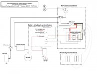
I've attached my most recent drawing which updates the forward plug and adds the EMS. I haven't decided yet where to *physically* place the EMS due to the length of the control cable. I may have to put it on the forward wall of the basement, or figure out how to build a longer cable. The 220V wiring would be a little easier if I can put it in the forward compartment with everything else.
Tim
He again reiterated their recommendation that nothing is placed between the shore power connection and the EMS. When I pressed with questions about transfer switches, he invoked the "I'm not an expert on transfer switches". Then I noticed they actually have page 6 in their installation manual (that Joe linked) that talks about how to place the EMS after a "transfer box". From what I can gather, his primary concern was someone functioning the switch incorrectly. Not sure, but I think others have the kind of setup I'm describing?
He also said we shouldn't simply turn off the EMS while on generator unless something is done with the ground. I need to research this further.
I've attached my most recent drawing which updates the forward plug and adds the EMS. I haven't decided yet where to *physically* place the EMS due to the length of the control cable. I may have to put it on the forward wall of the basement, or figure out how to build a longer cable. The 220V wiring would be a little easier if I can put it in the forward compartment with everything else.
Tim
Tim,
Looks like you have a good handle on it. The Go Power inverter answers a lot.
I presumed you are looking at THIS Progressive Industries 50 amp unit. I have the 30 amp model. The switch on the remote display puts the unit in bypass. If this is the one you are thinking of using and you haven't done so already, take a look at the installation guide HERE. It gives a lot of information. Especially pay heed to page 3 regarding not connecting it to an inverter.
Attachments
StrongJava
Well-known member
Thanks. They do seem to recommend putting it before the transfer switch, but they don't say why.
What do you have for a transfer switch?
What do you have for a transfer switch?
If you are going to use a 120v 30a generator you can make a "cheater" plug for it to satisfy the EMS. My EMS is before the transfer switch. That was their suggestion when I wired it????
avvidclif
Well-known member
Thanks. They do seem to recommend putting it before the transfer switch, but they don't say why.
What do you have for a transfer switch?
Progressive Dynamics PD-52. It's the stock unit. They told me the generator had all the protection it needed built-in and the EMS should protect on the 50A pole connection.
StrongJava
Well-known member
Thanks. It sounds like you have an auto start generator? I do not. Plus, I want to be able to use the plug I'll add up front for shore power in those places where they put the pedestal up front. We've run across that a handful of times in just the last year.
Progressive Dynamics PD-52. It's the stock unit. They told me the generator had all the protection it needed built-in and the EMS should protect on the 50A pole connection.
StrongJava
Well-known member
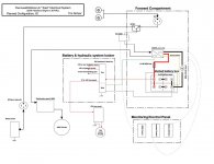
After more consideration, I've decided to forego the transfer switch and additional plug. A simple extension cord provides more flexibility, is less work, probably weighs less, and doesn't require as complicated of wiring. I'll still be running 6/3 with a ground from the EMS I'll mount in the utilities area, up to the front compartment to go through the inverter, and then back to the distribution panel.
I've attached what I think is my final system drawing for historical purposes.
I've attached what I think is my final system drawing for historical purposes.
Attachments
StrongJava
Well-known member
Re: Planning Electrical Mods--Mounting Inverter
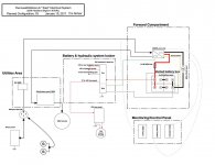
I'm close to starting the actual install, and am trying to finish the drawings for where to mount components.
The inverter manual provides a warning about mounting on flammable material. What is the material on the wall in the front compartment and should I consider it flammable for this application? Would it be better if I got a piece of plywood for mounting all the components onto? I don't mind, just don't want to add the weight if not necessary.
Thoughts?
Thanks.
Tim
Attachments

TravelTiger
Founding Texas-West Chapter Leaders-Retired
We mounted ours with a piece of sheet metal between it and the wall.
Sent from my iPhone using Tapatalk
Sent from my iPhone using Tapatalk
Similar threads
- Replies
- 7
- Views
- 581
- Replies
- 6
- Views
- 928