And so it begins

iforget

New Jersey Chapter Leader-retired
After I had Duane stop using our fireplace because of the Parrot, we gave our neighbors a very nice log rack and all the wood!
He is just so clever! At least the axles now have a purpose. Now, how about those tires? I am thinking of making them into an herb garden soon. Or drop them by the reef for a Lobster love shack..
 

bgassie

Member
I had obtained extra material while at the factory. Here is one of the projects. Although the tailor I brought this project to assured he could make sliding door drapes, his skill level is not quite up to what I was expecting.


Porthole, I was thinking of doing the same. What type of rod hanger did you use?
 

porthole

Retired
Home Depot
I'll take pictures when I can, but just a simple wood curtain rod. Color was close, it is fluted and the wall brackets were right next to at the store, as well as the rings.

Wood was the cheapest option which works fine just to see if this was going to be OK. But anything is better then the pitiful vertical blinds that came with the rig.
 

recumbent615

Founding MA Chapter Leader-retired
Re: Ladder

The ladder for these trailers is just a bit long. It is long enough that it doesn't fit on the bunks.

I found a bunk ladder at RV Surplus and adapted it to the Cyclone ladder.
Now I have two short ladders.


Duane,

Do you know the mfg and model of the bunk ladder you found? I've been looking to replicate what you have done and I'm not having any luck finding the same style bunk Ladder. I assume that you move the stand-offs from the lower section of the OEM ladder and attached them to the upper part of the bunk ladder.

Thanks for any additional information you can provide on this Mod.
 

porthole

Retired
Re: Ladder

Kevin, I picked it up at the RV wholesale shop in Elkhart when I had picked up the trailer in 2009.
I went back there this year with SpringerDan as he wanted to do the same thing. There were two of the same ladders in the store at the time.
So I would think that would be the best option, call, see if you can send a picture for them to match up.
They had dozens of ladders in stock, probably in excess of 50 all styles and shapes, so a picture would be best.

I'm guessing here, but IIRC I cut the Cyclone ladder, removed the standoffs from the cut piece and installed them on the short ladder.
I think I also moved the standoffs that came on the short ladder to bump up right at the edge of the J-wrap. My thoughts were that this would be the strongest area for the standoff's. I also considered adding a piece of 2" aluminun angle, glued on to the J-wrap for additional support. But I never saw this to be an issue. You are taller and bit heavier then me so it might be more of an issue.

If you want I could get the ladder out, take a better picture and measure it.

//heartlandowners.org/showthread.php/11365-And-so-it-begins?p=82012&viewfull=1#post82012
 

recumbent615

Founding MA Chapter Leader-retired
Re: Ladder

Duane,

Do you recall what the name of the RV surplus outlet was - there seems to be a ton of them in Elkhart. Also if you get a chance measurements and a better photo would be great ... I am not a small person and yesterday when I was attempting to get on my Roof - three rungs broke on the OEM ladder so I may be looking into a better quality ladder Rung as well ... All metal would be better than the plastic end caps.


Thanks for all your help...

Kevin
 

porthole

Retired
Duane,

where did you pick up power for the LED?

Kevin

Right off the switch.
The LED came from West Marine, mainly because it is convenient for me. But any 12 volt LED will work. I also wanted something small. That LED is just bright enough to be seen but not be "in your face"
 

recumbent615

Founding MA Chapter Leader-retired
Duane,

Thanks - I've started started the "Duane" upgrades for my 3010 ... :rolleyes:. so far I have added two additional electrical outlets on the entertainment center, moved the basement Vac outlet, and rerouted the winterizing hose. Tomorrow I will tackle the wall under the sink and install a new floor after rerouting the plumbing so it is out of the way. The LED will have to wait until I can find a suitable one. I also plan on running two additional Circuits ( 20A ) out to the Garage area to power the computer equipment at the desk ( I still need to build that ) and a supplemental wall mount heater. All that under carriage work will have to wait until we have some slightly warmer weather - The Desk I hope to start later this month.

Thanks for the Inspiration and in some cases the Ideas that I am stealing outright.

Kevin
 

porthole

Retired
Duane,

Thanks - I've started started the "Duane" upgrades for my 3010 ... :rolleyes:. so far I have added two additional electrical outlets on the entertainment center, moved the basement Vac outlet, and rerouted the winterizing hose. Tomorrow I will tackle the wall under the sink and install a new floor after rerouting the plumbing so it is out of the way. The LED will have to wait until I can find a suitable one. I also plan on running two additional Circuits ( 20A ) out to the Garage area to power the computer equipment at the desk ( I still need to build that ) and a supplemental wall mount heater. All that under carriage work will have to wait until we have some slightly warmer weather - The Desk I hope to start later this month.

Thanks for the Inspiration and in some cases the Ideas that I am stealing outright.

Kevin

If you don't get it before hand, let me know before the next rally and I'll grab the LED.

Outlets - yes we need outlets. I did a 20 amp in the garage this past summer. That single outlet at the top of the storage cabinet in the far corner - just doesn't cut it.

I have a flat wall mount heater in my motorcycle trailer. Does a fair job.

I'm waiting another month or so before pulling the cover off. Have no desire to work on it yet.
I do have a 2KW inverter to start thinking about installing. Maybe even permanently add my solar panel to the roof. Right now I have a 15 watt panel tied to the AC unit.
I leave the batteries in and this year I didn't not have to plug in the shore power.

Don't remember if you have a genny. But one of my projects is to also wire in a receptacle so that I can plug in circuits from the house for the next power failure.
After Irene passed through I was using my Honda 3000 for several days. Worked OK but the Cyclone has 25 gallons of gasoline. Just wish it was 240!
 

recumbent615

Founding MA Chapter Leader-retired
Duane,

Do you recall how the awing is wired ? I saw that you said that it is always powered - I assume that you mean that it always has power to both in and out leads. I see that the switch has the following connections

Ground
12v DC
motor wire A
motor wire B

I assume that with the switch in the neutral position there is 12v on both motor wires
and on movement only one of the motors has power.

Does the other motor wire get ground? or does it float?

Asking before I go out and start looking at it my self .

I can not find any documentation on how this works. I did find the installation docs but it provides no insight on what is actually going on at the motor.

thanks for any insight you may have


Kevin
 

porthole

Retired
Do you recall how the awing is wired ? I saw that you said that it is always powered - I assume that you mean that it always has power to both in and out leads. I see that the switch has the following connections

Ground
12v DC
motor wire A
motor wire B

I assume that with the switch in the neutral position there is 12v on both motor wires and on movement only one of the motors has power.

Does the other motor wire get ground? or does it float? Asking before I go out and start looking at it my self .

I can not find any documentation on how this works. I did find the installation docs but it provides no insight on what is actually going on at the motor.

Hey Kevin
The simple answer is - I don't remember :cool:

Are you trying to do the same thing I did with the additional switch? My post mentioned that I had a couple of blown fuses before I realized the motor has the brake. Not sure how that worked either, but that was the reason for a "in/out" selector switch for the basement switch.

As long as you are not in a hurry I can look to see exactly what I did with the wiring. The trailer will be wrapped up at least for several more weeks.

//heartlandowners.org/showthread.php/11365-And-so-it-begins?p=93541&viewfull=1#post93541
 

recumbent615

Founding MA Chapter Leader-retired
Duane,

I am looking to do a similar mod to yours but was thinking about how this was wired giving your original comments, and believe that it may be possible to change the switch out with relays and then have two normal two position momentary switches control the relays. it is a bit of a challenge making/planning mods to systems that are totally undocumented! I'll take out my MM this week and start poking around.

thanks

Kevin
 

porthole

Retired
This DPDT thing we are discussing for those that don't know what we are referring too.

A DC motor rotates based on how the plus and minus leads are attached. Connected one way and the motor spins clockwise. Reverse the leads and the motor reverses.
The switch on the inside of my trailer is a double pole-double throw.

A DPDT switch will have 6 terminals. These are a 3 position "on-off-on" switch. And they can be a momentary on (you hold the switch on, think horn button)

By using just one side of the switch you can turn on two different items, on-off-on.
By using both sides you can turn on 2 items as above
Or, by cross jumping the terminals you can reverse the current to one item.

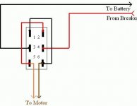
In this picture, Black battery = negative, Red breaker = 12 volt positive from the breaker or fuse.
The orange and brown are neither + or - until you connect power.

Using this picture:
3 and 4 are battery - and +

Flip the switch up and and the circuits completes as 3 to 5, 4 to 6, 12v+ to brown, 12v- to orange
Flip the switch down and and the circuits completes as 3 to 1, 4 to 2 - but you can now see that 12v+ is now supplied to orange and 12v- to brown.
This reverses the DC motor.

You do this with the wiring, it is not internal to the switch.

DPDT_switch_5.JPG
 

Attachments

  • DPDT_switch_1.jpg
    DPDT_switch_1.jpg
    15.9 KB · Views: 73

porthole

Retired
Duane,

I am looking to do a similar mod to yours but was thinking about how this was wired giving your original comments, and believe that it may be possible to change the switch out with relays and then have two normal two position momentary switches control the relays. it is a bit of a challenge making/planning mods to systems that are totally undocumented! I'll take out my MM this week and start poking around.

thanks

Kevin

Of course relays will work, but I think that just complicates it unnecessarily. Unless you like playing around.

On my new truck I wanted to activate the electric locks on my tool box. The locks use a DC reversing solenoid.
The new trucks use a body computer to control all operations. So when you activate the door locks all you are doing is sending a pulse to the lock circuit. The truck locks work effectively with this pulse. The tool box, being "old school" need 12 volts applied for more then a fraction of a second.

What I did was use relays. It took 4 relays to get the desired result! I used the standard automotive relay as I had all that I needed instead of some big fancy multi pole relay
 

Attachments

  • Locks_&_relays_03.jpg
    Locks_&_relays_03.jpg
    401.6 KB · Views: 131
  • Locks_&_relays_04.jpg
    Locks_&_relays_04.jpg
    485.2 KB · Views: 136
  • Locks_&_relays_05.jpg
    Locks_&_relays_05.jpg
    180.9 KB · Views: 135

recumbent615

Founding MA Chapter Leader-retired
Duane,

Opened the switch panel and here is what I found. pins 3 & 4 go to the motor (normally open) pins 5 & 6 have 12v and GND, and hardwired with a jumper on the back pins 1 & 2 have ground and 12 V. Given this I can not see why we can not just add a second switch outside to provide power to the motor in the same way since there is no power to the motor in the neutral position? provided the switch is exactly the same it should work. Am I missing something?
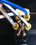
The top of the switch is at the bottom of the photo

IMG_0797[1].jpg

Kevin
 

porthole

Retired
Opened the switch panel and here is what I found. pins 3 & 4 go to the motor (normally open) pins 5 & 6 have 12v and GND, and hardwired with a jumper on the back pins 1 & 2 have ground and 12 V. Given this I can not see why we can not just add a second switch outside to provide power to the motor in the same way since there is no power to the motor in the neutral position? provided the switch is exactly the same it should work. Am I missing something?


DPDT_awning_switch.jpg


Is this right?
1 (top left) = white 12 volt +
2 = blue 12 volt -
3 = white (with lettering)
4 = white with blue trace
5 = jumped from blue
6 = jumped from white

I'll try and get in to look at my switch later. I don't remember what it look like.

But - looking at this, it seems you only would need to run two wires from the remote location, and join them to the two motor wires at pin 3 & 4. You could pick up 12 volt + & - at the new switch location if desired.

Since both the original and additional switch would be normally open it wouldn't matter where the 12 volt supply to the motor came from.

Really have to look at my switch, mine was not that simple, or as simple as I am making this out to be. My awning is a Carefree, yours?
 

recumbent615

Founding MA Chapter Leader-retired
you are correct - it appears simple - I just ordered a switch to install in the cellar - it will be here on Friday.

I have not determined exactly what awning I have - but I expected that it was a Carefree since that is the brand that is listed on all the documentation for the 2010 Cyclone 3010. I guess I can call heartland and ask.

Kevin
 

recumbent615

Founding MA Chapter Leader-retired
Update - new switch arrived and has been installed - no need for toggle switch in my case. just tapped 12v and ground from the overhead light in the garage and sent the center terminals from the switch up to the stock switch and spliced the two wires ( original and new ) for the center of the original OEM switch - easy peasy

Kevin
 
Top