Cyclone 3010 Battery Upgrade

watchthebox

Well-known member
Today I finally finished installing new batteries in my 2011 Cyclone 3010. The original single 12V battery from the dealer just didn't have enough juice.

My overall plan is to install new batteries, add an inverter, and add solar to my Cyclone. Here are some pictures of the progress so far:

Just getting started, original battery.
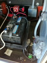
Before Battery Compartment.jpg

Old battery removed, braces installed ready for new battery box.
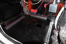
IMG_0266.jpg

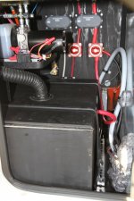
New battery box installed, note elevation of hydraulic unit with 2X4 scraps which was necessary to squeeze box into small spot.
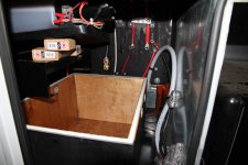
Hydraulic unit raised.jpg

4 new Trojan T-105 Plus batteries installed and wired up. It was a bit of chore getting these heavy batteries under the hydraulic unit and into the box. My back is feeling it.
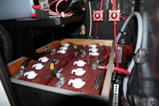
Installed batteries in box.jpg

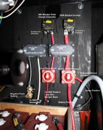
New power center with battery disconnect switches, buss bars, and circuit breakers for upcoming inverter and solar installation. I custom made the cables with 2-0 AWG and 6 AWG marine cable. My new hydraulic crimper's getting a lot of use!
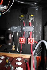
Power Center.jpg

It's taken more work than I had imagined, as is often the case, in no small part due to having to work in that small compartment. Next up inverter install, then onto solar!
 
Last edited:

Riverman

Well-known member
Great Job.
I switched our 1-12V for 2-6v last summer.
Quite an improvement....would have liked 4-6v but didnt believe I had room.
May need to reconstruct my box.
I will be waiting for your how-to and pictures for the remainder of your power management sytem
 

porthole

Retired
Hard to tell from the pictures.

Looks like you are wired up for 4-6 volt batteries - series parallel, giving you the capacity of the four batteries tied into one 12-volt output, yes?

What are the black boxes between the switches and breaker?

The battery switch on the pictures right is obvious, what is the second one for? Fed from where?

Is that a fuse or shunt on the black cable?

Which crimper are you using?

Nice work so far.

This is in my plans, but the batteries are pricey and I think I need 6 for the golf cart first :confused:
 

watchthebox

Well-known member
porthole, yes, the four 6V batteries are wired in series and parallel for a 12V bank.

The dark gray rectangular things are 300A buss bars. A little overkill, but it made hooking things up a little easier and neater.

The red switch on the left is the disconnect switch for the RV loads. That on the right is the main battery disconnect switch. Again, somewhat overkill, but there will be times I want the batteries still connected, e.g. so they can get charged with solar when stored/parked.

The device hooked up to the black cables on the left is indeed the shunt. I haven't hooked up the inverter, which uses a common remote control panel for it and the battery monitor/shunt.

I use a 12 ton hydraulic crimper. I bought several of them a while back and have been selling them on eBay: http://cgi.ebay.com/ws/eBayISAPI.dll?ViewItem&item=320650630859&ssPageName=STRK:MESOX:IT

Thanks for the compliment. It's a fair amount of work, but it's rewarding and a good learning experience. Also, if you do it yourself, you know it's done right.
 

porthole

Retired
Switch on right - main disconnect. Feeding the buss, buss then feeding two breakers and the disconnect on the left - going to the RV load.
Right switch - heavy wire to Genny?
where are you going to feed your inverter?

What size breaker does your inverter recommend? The largest surface mounts I could find are 150 amps.

The wire coming into the bottom of the shunt, is that the negative cable right off the battery?
If I am looking at this correctly, your ammeter will always have a reading, even if the batteries are off but the solar is providing power.
 

watchthebox

Well-known member
Switch on right - main disconnect. Feeding the buss, buss then feeding two breakers and the disconnect on the left - going to the RV load.
Right switch - heavy wire to Genny?
Correct. The black 2AWG cable connected to the right side of the right red disconnect switch is power to the genny to start it. The smaller 10AWG cable next to it is the other always hot wire. I haven't figured out what it is yet. I posted a question about this awhile back, and some thought it might be to the brakes. Regardless, it's hooked up similar to OEM.

where are you going to feed your inverter?
The positive will come off the load connection from the 150A circuit breaker. The negative will go to the negative buss bar.

What size breaker does your inverter recommend? The largest surface mounts I could find are 150 amps.
Yeah, that's the largest I found too (150A). I originally was planning to have an 1800W Xantrex Prosine inverter, but was concerned it wouldn't have enough pass through capacity (Only 15A) to power the three circuits I'm going to break off in the subpanel (20A microwave and two 15A outlet circuits). So I decided on a Magnum MS2012 (2000W) inverter. Anyway, I was thinking that the 150A breaker was going to be enough for the 1800W inverter and purchased it. I really like that breaker, as it also acts as a nice switch, so I figured I'd try it with my larger inverter. Evidently the max recommended breaker for 2/0 cable in conduit is 175A. I'm not putting my DC cable in conduit, but figure (hope :rolleyes:) I'm not too far off with the 150A breaker. Worst case my inverter will trip the breaker all the time and I'll have to get a 300A fuse.

The wire coming into the bottom of the shunt, is that the negative cable right off the battery?
Yes.

If I am looking at this correctly, your ammeter will always have a reading, even if the batteries are off but the solar is providing power.
I'm not sure. Would that be a good thing?

Thanks for you input. I hope I've thought things through correctly and don't blow up my Cyclone! At least the DC stuff works so far.
 

watchthebox

Well-known member
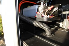
I installed the vent on the lid of the battery box. I think it turned out well. I hope the ventilation is adequate. Here are a couple pictures with the vented lid:

Battery Box With Vented Lid.jpg

Vent to Outside.jpg

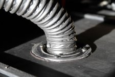
I wish I could remember who on this forum talked about this way of attaching the vent to a new box so I could give them credit. It's a good idea. I just cut off the vent attachment flange from the old battery box and screwed it onto the new lid with a little silicone sealant.
Lid Vent Detail.jpg

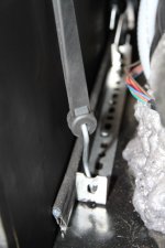
Here's a close-up of battery box tie-down anchors. I was trying to come up with a simple way to anchor the tie-downs. I ended up just cutting the end of the brace and bending it 90 degrees to provide an attachment point for the tie-down hook. It was cheap and works well.
Tie Down Anchor Detail.jpg
 
Last edited:

watchthebox

Well-known member
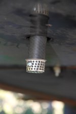
I also added a vent on the bottom of the battery box. It's 3/4" ID rubber hose, which a drain cover screwed to the end to keep bigger bugs out. I'm not sure if it is needed, but the original one had one, and it kind of makes sense that it would vent better if there is an inlet and oulet to the box. Is there a general consensus on this?

Battery box bottom vent (view from under 5th wheel):
Battery Box Bottom Vent.jpg
 

Vtxkid

Well-known member
I also added a vent on the bottom of the battery box. It's 3/4" ID rubber hose, which a drain cover screwed to the end to keep bigger bugs out. I'm not sure if it is needed, but the original one had one, and it kind of makes sense that it would vent better if there is an inlet and oulet to the box. Is there a general consensus on this?

Battery box bottom vent (view from under 5th wheel):
View attachment 11930

Creative & Clean looking... I like it!
 

2010augusta

Well-known member
Philip, I think your " Unknown always hot wire" could be the power to the break-away switch. Just a though.

Great looking work by the way.
 

porthole

Retired
When I added a sealed battery box (no vent in the bottom) I added an issue, minor, but something.

Rain and wash water get in the front mounted vent, keeps the battery wet (potential for current draw across the wet surface).
I will be relocating the vent, maybe out the bottom let it vent by venturi effect.

With the original setup water drains out the bottom, mixed with whatever acid is on the battery surface.
The mixture was corroding the surrounding area of the bottom drain, including my hydraulic disc brake line.
 

porthole

Retired
Battery off-gassing and more pronounced with the cheap automotive starting batteries typically installed in the RV's.

Your GC batteries with a good charger (Cyclones come with the "smart charger") should have minimal gassing issues.
 
Last edited:

watchthebox

Well-known member
Thanks for letting me know. I'll have to watch to not get water in the vent when washing, and to keep an eye out for any acid leaking out the bottom vent.
 

porthole

Retired
The smaller 10AWG cable next to it is the other always hot wire. I haven't figured out what it is yet. I posted a question about this awhile back, and some thought it might be to the brakes. Regardless, it's hooked up similar to OEM.

I have one too I am trying to trace. It is on a separate 30 breaker

The positive will come off the load connection from the 150A circuit breaker. The negative will go to the negative buss bar.

Yeah, that's the largest I found too (150A). I originally was planning to have an 1800W Xantrex Prosine inverter, but was concerned it wouldn't have enough pass through capacity (Only 15A) to power the three circuits I'm going to break off in the subpanel (20A microwave and two 15A outlet circuits). So I decided on a Magnum MS2012 (2000W) inverter. Anyway, I was thinking that the 150A breaker was going to be enough for the 1800W inverter and purchased it. I really like that breaker, as it also acts as a nice switch, so I figured I'd try it with my larger inverter. Evidently the max recommended breaker for 2/0 cable in conduit is 175A. I'm not putting my DC cable in conduit, but figure. I'm not too far off with the 150A breaker. Worst case my inverter will trip the breaker all the time and I'll have to get a 300A fuse.

Tried out the inverter yet? Most of what I have seen is to recommend a 300-400 amp fuse. In wiring a fuse block in mine now, for future inverter use.
 
Top