The molding probably can't be easily found for a 2014. The designs change over the years. It's possible, but low odds, of finding a match at an RV surplus location - there aCre some in Elkhart but that may not be close to you. You may have to replace with a close match, or replace all of the molding if getting it to look the same is a priority.
Rewiring the control panel will be challenging. Most of the switches look to be handling 12V DC. Two look like 120V AC. The awning recept is likely to switch 120V AC on and off at the receptacle on the front of the RV, door side. The 120V Water Heater switch might be switching 120V AC directly, or it might be 12V DC, operating a relay that switches the 120V AC.
Take a voltmeter set to read AC voltage and see if you can identify one or maybe two hot wires that read 120V AC. Once you find the wires, look at your circuit breaker panel and turn off the water heater breaker to see if it cuts power to one of those wires. That would identify the one that goes to the water heater switch. If a breaker is marked for the awning receptacle, same for it. Connect those hot wires to the appropriate switches. To find the wire that goes to the awning receptacle, you'll need a long wire for a continuity test to the hot (short) side of the receptacle. But, in testing, you need to first cut off the circuit breaker for the Power Converter, and set the battery cutoff to OFF so you don't do a continuity test and hit 12V DC hot wires. A continuity test on the water heater, assuming you found a 2nd 120V hot wire, would require cutting off all AC and DC power, and putting one lead on the heating element where the wire from the thermostat/ECO attaches (assuming a Suburban water heater). On an Atwood, you'd probably have to find where 120V AC goes into the water heater circuit board and put the lead there. These are probably 2 person tests.
Once ALL of the 120V AC hot wires have been connected and are out of the way, you can do continuity checks between the fuse box and individual wires (with all DC power OFF). to match fuses to loose wires to switches. You'll want to connect all of the wires getting power from the fuse box. That'll leave the wires that feed 12V to the various lights and other switched devices. With DC power ON, you should be able to touch and individual wire to a hot 12V wire on a switch to see what lights up. I'd expect you could identify and connect up the various light switches that way. If you do this with a faucet open, when you hit the water pump, you should hear it start up.
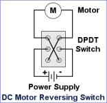
The awning retract/extend is trickier. Connecting that wire to 12V will cause the motor to run and you should hear that if the door is open. But rocker switches are wired differently so they can reverse polarity. Wiring is probably like this.

In all of this, make sure to NOT apply 120V AC to a 12V circuit.
 20210701_130712.jpg
 20210701_134456.jpg
 20211114_155303.jpg
 20211114_155315.jpg

 20211114_155330.jpg
