Need help with fuse panel mystery

David-and-Cheryl

Well-known member
This is kind of a long set-up, but I wanted to provide as much information as possible to help troubleshoot this mystery.

Some months ago, I pulled a brand new circuit from our Progressive Dynamics PD60 12v power distribution center to our nearby tech cabinet, which houses our WiFiRanger router and Netgear hotspot. I connected the circuit to one of the unused fuse connections (#17) at the bottom of the fuse panel, which already had a 15A fuse in it. The cabinet end of the circuit terminates in a combination 12v lighter socket/2 USB adapter. The WiFiRanger was plugged into that using its lighter socket power adapter, and everything has worked well.

Recently, however, we started noticing that the external antenna that the router powers was rebooting itself frequently. While troubleshooting that problem, WiFiRanger support suggested that our 12v power might be the cause, and noted that the router works best on 24v when it has to supply power to connected devices like the external antenna and hotspot. They recommended that we get the 24v step-up converter that is now included with their newer systems.

So, I ordered that converter, spliced it in to the tech cabinet circuit just before the lighter socket/USB adapter, and plugged in the router. After that, things went haywire. Our ceiling lights in the bathroom and bedroom all went out. I checked the fuse panel and fuse #5 was blown. Note that this is a completely different circuit from the one powering the tech cabinet. I unplugged the router, replaced fuse #5 and power was restored to the lights.

However, when I connected the 24v converter to the router, the fuse blew again and the lights went out. The router, however, had normal power.

It gets weirder. When I pulled the power plug out of the router, I noticed that the lights flickered. So I pulled fuse #5 (the one for the lights), but before I replaced it, I plugged the router back in. Just as the plug made contact with the router, the lights came on, even though there was no fuse for the lights in the fuse panel. Then when I pushed the power plug all the way into the router, the router came on, and the lights went out (although a couple of them are actually on but very dim--they are LEDs). Finally, with the router connected to power, I can't get the lights to come on, even with a working 15A fuse in the panel. I also tried a 20A fuse with the same result. The 12v power adapter for the router does the same thing, even though it used to work fine. No other 12v circuits in the trailer are affected as far as I can tell.

It looks like what's happening is that when the DC power plug from either the 24v converter or the 12v lighter socket adapter is shorted, a circuit is somehow completed to the lights, even though that should be impossible with the fuse out of the panel. But when the power plug is actually powering the router, it overloads the light circuit, blowing fuse #5, and the lights go out because there isn't enough current "leaking" from circuit #17 to also power the lights. Somehow the mere presence of the 24v converter is causing all of this, even when it's not powering the router.

Can someone PLEASE tell me how to go about diagnosing and resolving this problem? Those should be two completely different circuits, but obviously they're not.
 

Jesstruckn/Jesstalkn

Well-known member
That is very confusing without seeing it in person.
Sounds to me like a ground issue. Or swapped wires somewhere.
Your new circuit is feeding juice to the other cercit through the ground.
I would undue everything you added and get everything working correctly the double check the polarity of the new equipment before you reconnect it.


Sent from my XT1585 using Tapatalk
 

richheck

Seasoned Member
I agree with Jerrod. I was having issues installing a dimmer in my bedroom reading lights in my 2017 LM 365 Arlington. Both Jerrod and I were stumped for a bit. Finally after testing the wires to the light we found the factory had put the switch to the light on the ground wire, not the hot wire. Reversed wires and the install went perfect.

in addition, fuse #17 on my coach is for the Yeti package that I don't have.
 
Last edited:

cookie

Administrator
Staff member
Wow, you sure have a lot going on.
Here is what I got from that. Since you have LED lighting and the lights are very dim when the fuse is pulled, that is normal.
There is a small amount of power that will still light the lights, as that is what illuminates the red blown fuse indicator.
Whey you plug your router in, without that fuse and the light then get bright, it indicates to me that something is not wired correctly as you somehow close the circuit to allow a full 12 volts to flow.
Like Jerrod suggested, you might want to restore the original circuit wiring and start anew.

Peace
Dave
 

danemayer

Well-known member
Some months ago, I pulled a brand new circuit from our Progressive Dynamics PD60 12v power distribution center to our nearby tech cabinet, which houses our WiFiRanger router and Netgear hotspot. I connected the circuit to one of the unused fuse connections (#17) at the bottom of the fuse panel, which already had a 15A fuse in it. The cabinet end of the circuit terminates in a combination 12v lighter socket/2 USB adapter. The WiFiRanger was plugged into that using its lighter socket power adapter, and everything has worked well.

I've highlighted the things that caused me confusion right at the start.

What is a Progressive Dynamics PD60 12v power distribution center (can't find such a thing on the PD website)?

What do you mean "pulled a brand new circuit" from the PD60 to connect to fuse #17?

Why do you think fuse panel position #17 which already had a fuse in it was unused?

I'm developing a picture in my mind that maybe you added new, parallel wires from the output of your PD9200 Power Converter to some terminal on your fuse panel, and ran wire from the load side of 17 to your devices.

Can you unconfuse me.
 

David-and-Cheryl

Well-known member
Dan, answers to your questions below, with photos.

What is a Progressive Dynamics PD60 12v power distribution center (can't find such a thing on the PD website)?

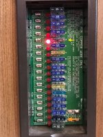
It's how the printed circuit board that holds the fuses is labeled. See following photo. I couldn't find any documentation on it either. The circuits are numbered 1 to 18 from top to bottom. The yellow arrow points to circuit #5, which is the bedroom and bath lights. The orange arrow points to circuit #17, which is where I connected the new wires to the tech cabinet. (In the photo, the numbers on the PCB appear not to align with the fuses, but that's just due to parallax; in real life they line up.) EDIT: apparently it's now called a 6000 series DC distribution panel.

fuse panel.jpg

What do you mean "pulled a brand new circuit" from the PD60 to connect to fuse #17?


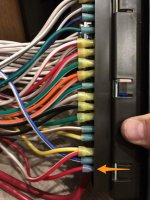
Using 14 gauge primary wire, I connected a length of red wire with a female quick connector to the positive side of circuit #17 (orange arrow):

fuse panel - positive side.jpg

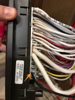
...and a length of black wire to the common ground block at position #17 (orange arrow):

fuse panel - ground side.jpg

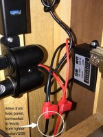
Those two wires run to the tech cabinet, where they are connected to the lighter socket/USB:

tech cabinet wiring.jpg

Earlier today, I used the red quick splice connectors to splice in the 24v step-up converter for the WiFiRanger. (I initially suspected that, but I've since clipped the wires to the converter and the problems with the lights still exist, so I've eliminated that as the cause.)

Using my DMM, I've confirmed that the polarity at the plug end of the 12v lighter adapter is correct--it's supposed to be center-positive and it is.

Why do you think fuse panel position #17 which already had a fuse in it was unused?

Because there was nothing connected to the positive side of circuits #17 or #18, and as far as I could tell, nothing in the trailer turned off when I pulled those fuses. Only circuits 1-15 were labeled by Heartland inside the cover of the fuse box, but #16 definitely has a wire connected to the positive side, although I don't know what it powers. (For what it's worth, #17 previously had a 20A fuse in it, which I replaced with a 15A when I pulled the new wiring, and #18 had and still has a 35A fuse in it. I have no idea why--possibly something the prior owner put in there.)

I'm developing a picture in my mind that maybe you added new, parallel wires from the output of your PD9200 Power Converter to some terminal on your fuse panel, and ran wire from the load side of 17 to your devices.

I don't think so...I didn't run anything from the PD9200 directly; the only connections I made were the two at the fuse panel described above. But obviously, power is somehow getting from circuit #17 to circuit #5 when it shouldn't be. I thought Jerrod might be on to something with the idea of power flowing through the ground to the other circuit, but I can't for the life of me figure out how that could happen.
SaveSave
 

danemayer

Well-known member
The additional info and pics help a lot.

I agree with the earlier comment that you may have a ground problem with the coach. I would take down the rear wall of the pass through basement storage and trace the ground wires from the fuse panel and from the negative terminal of the battery. See where they attach to the frame and make sure you have a clean, tight connection and that the wire crimps are not loose. Also check for good connections on the Power Converter and at the battery, and of course where the thick wires attach to the fuse box. I'd suggest turning everything off, including the battery cutoff(s) while doing this.

The second thing I'd suggest is taking the WiFi ranger voltage converter out of the loop, at least for the time being. It may be a simple transformer or it may have active electronics. In either case, the operation and potential for the unexpected is an unknown. And since your mystery started when you added it, you don't need it complicating the situation.

The third thing would be to eliminate the quick connects. They may be the source of the intermittent re-boots. It's not unusual for quick connects to have problems. Replace them with Wago Lever Nut Connectors. You can buy an assortment that allow connection of 2, 3, or more wires, or just get the sizes needed. In the short term, a regular wire nut will do.
 

David-and-Cheryl

Well-known member
I agree with the earlier comment that you may have a ground problem with the coach. I would take down the rear wall of the pass through basement storage and trace the ground wires from the fuse panel and from the negative terminal of the battery. See where they attach to the frame and make sure you have a clean, tight connection and that the wire crimps are not loose. Also check for good connections on the Power Converter and at the battery, and of course where the thick wires attach to the fuse box. I'd suggest turning everything off, including the battery cutoff(s) while doing this.

Whew, OK, I can do that, but it's not easy. If the grounding problem was outside the fuse box--i.e., at the frame, the battery or the power converter--wouldn't it affect all the circuits, not just #5, since all the circuits share a common ground block?

The second thing I'd suggest is taking the WiFi ranger voltage converter out of the loop, at least for the time being. It may be a simple transformer or it may have active electronics. In either case, the operation and potential for the unexpected is an unknown. And since your mystery started when you added it, you don't need it complicating the situation.

Agreed - I actually did that right after I took the photos, but to no avail. I was able to reproduce the problem with the 12v lighter adapter that I'd been using up until today. The difference is apparently that the 12v adapter doesn't draw enough current to pop fuse #5, but the 24v transformer does (which makes sense), so that's when I became aware of the problem. But the problem obviously was lurking already.

The third thing would be to eliminate the quick connects. They may be the source of the intermittent re-boots. It's not unusual for quick connects to have problems. Replace them with Wago Lever Nut Connectors. You can buy an assortment that allow connection of 2, 3, or more wires, or just get the sizes needed. In the short term, a regular wire nut will do.

If you mean the quick connects on the wires shown in the last photo, those were just installed today as part of the WFR voltage converter installation. They weren't there when we were having the rebooting problem--the lighter socket/USB assembly was connected to the wires from the fuse box with wire nuts.

I had one other thought: is the PCB in the fuse box possibly defective, allowing current to flow where it shouldn't?
 

danemayer

Well-known member
Whew, OK, I can do that, but it's not easy. If the grounding problem was outside the fuse box--i.e., at the frame, the battery or the power converter--wouldn't it affect all the circuits, not just #5, since all the circuits share a common ground block?


Agreed - I actually did that right after I took the photos, but to no avail. I was able to reproduce the problem with the 12v lighter adapter that I'd been using up until today. The difference is apparently that the 12v adapter doesn't draw enough current to pop fuse #5, but the 24v transformer does (which makes sense), so that's when I became aware of the problem. But the problem obviously was lurking already.


If you mean the quick connects on the wires shown in the last photo, those were just installed today as part of the WFR voltage converter installation. They weren't there when we were having the rebooting problem--the lighter socket/USB assembly was connected to the wires from the fuse box with wire nuts.

I had one other thought: is the PCB in the fuse box possibly defective, allowing current to flow where it shouldn't?

Would a ground problem affect all circuits - you'd think so, but ground problems often produce difficult to explain results. Also, some circuits may have equipment that is more tolerant of abnormal conditions.

Ultimately, you're looking for some way to explain the apparent connection between the 2 circuits. Could it be the fuse panel? Low odds but maybe. You might try taking the wire on fuse #5 and moving it to #18 (if there's no wire there already) - with a change to the appropriate size fuse.

Barring a problem with the fuse panel, since your router wires are a completely new and separate run, the only other common point of the wiring is the ground connection.

Quick connects can be problematic, so I'd get rid of them anyway.

It might be interesting to see what happens with the 12V socket wires disconnected (not just router unplugged) and the WiFi Ranger wires connected. If there were some internal problem with the socket, the only way to know would be to take it out of the circuit completely.
 

David-and-Cheryl

Well-known member
Thanks Dan. I just removed the section of wire with the quick-connects and the lighter socket/USB socket from the system. Instead, I hardwired (with wire nuts) the 12v pigtail that came with the WiFiRanger directly to the wires coming from the fuse box. Same result. I would have been surprised if that was the problem, but you never know. At least I've eliminated both of those as possible problems.

I'll try moving the hot wire for circuit #5 to fuse #18 (with a 15A fuse) as you suggested, since that's easy. Maybe that would rule out bad circuitry on the PCB for #5 as the cause. And if that doesn't work, I'll go digging for the ground connections to check them.
 

cookie

Administrator
Staff member
Another option, which in this case I think would be a good one, would be to run an entire new fused circuit wire from the main 12 volt breaker buss. As well as a new wire direct from the neutral buss located nearby.
That should eliminate all the problems you are having at the 12 fuse panel.
Just a thought.

Peace
Dave
 

David-and-Cheryl

Well-known member
I tried moving the load-side wires for circuits 5 and 17 (one at a time, of course) to fuse #18, with no change. So probably not a defective fuse panel.

I'll check the grounds where I can, and if that doesn't work I may try Dave's idea to run new wires directly to the main 12v busses. Or, I may end up getting an electrician to help. ☹️

Thanks everyone. And if anyone else has any ideas, please share them.


Sent from my iPhone using Tapatalk
 

David-and-Cheryl

Well-known member
SOLVED! Re: Need help with fuse panel mystery

Well, after several attempts at troubleshooting this issue, I finally figured it out. It was indeed a grounding problem, but not where we thought.

I could see but not get to the chassis ground connection without major disassembly of the battery compartment (ours is on the side of the coach). So I ran a new wire from the positive buss bar near the battery and the negative terminal of the battery (we don't seem to have an accessible negative buss bar).

I first connected the other end of the positive wire to the 12v adapter for the WiFiRanger router...and to my surprise, with the negative wire still disconnected, the hallway lights came on, even though they were turned off at the switch. The router, however, did not come on. WTF, I thought? Then I realized that there had to be a ground running through the router somehow, even though it wasn't connected to one--or so I thought. I confirmed this with my multimeter.

I then disconnected my rooftop WiFiRanger Elite and Netgear AC791L hotspot from the Go2, and plugged them back in one at a time. Nothing happened when I plugged in the Elite, but when I plugged the hotspot back in to the Go2, the lights came on again. Somehow, current was flowing through the hotspot...but how? Its only electrical connection was through the USB tether to the Go2, which in turn was connected only to the positive side of the battery. More WTF...

Somehow, it occurred to me to disconnect the two cables from our rooftop MobileMark MiMo antenna from the hotspot. And when I did that, the hallway lights went out. Hmmmm? With either cable from the MobileMark antenna connected to the hotspot, the circuit was completed, and the lights came on. Then it hit me: somehow, the antenna was connected to ground.

I have that antenna mounted on an upside-down cake pan to provide a ground plane. The cake pan is then screwed to the roof of our rig with four 3/4" screws. I realized that somehow, one or more of those screws had contacted something grounded in the roof below the rubber membrane. Current was flowing from the Go2 to the hotspot, then from the hotspot through the antenna cables to the 7/8" threaded metal mounting post of the MobileMark antenna, and then through the cake pan and the screws into the chassis and back to the fuse panel, where it then (I guess) followed the path of least resistance through the hallway light circuit and back to ground. Holy cow!

To prove my theory, I unscrewed the cake pan/antenna assembly from the roof. Sure enough, the lights went out when I removed the last screw.

So I temporarily removed the antenna from the cake pan, and covered the mounting hole and both sides of the pan around the hole with electrical tape. I also covered the top of the mounting post to provide another layer of insulation between it and the cake pan. Re-mounted the antenna to the cake pan, and re-screwed the pan to the roof. Lights stayed off, and when I re-connected the 24v step-up converter--which is what started this whole thing--no fuses blew.

How crazy is that?? I wonder what's in the roof that is connected to ground? It seemed that any one of the four screws in the cake pan completed the circuit.

In any case, I'm glad that's over!
 

danemayer

Well-known member
I think the laminated roof on your rig has aluminum framing that must be connected to the aluminum framing in the sidewalls, which must be connected to the frame.
 
Top