danemayer
Well-known member
Yes they are. Especially when lying on your side in the basement with your legs hanging out the hatch.Those 6 gauge wires are a bear to manipulate.
Yes they are. Especially when lying on your side in the basement with your legs hanging out the hatch.Those 6 gauge wires are a bear to manipulate.
Alright gents, I got the EMS in today. Seems pretty easy, I installed the jumper cable into the input tonight here at the house and I'll take the unit out to the RV tomorrow and finish it up. Those 6 gauge wires are a bear to manipulate. I have but one question, the bypass switch on the remote display, which position should the with be in, up or down? I may be blind but I didn't see anything in the installation/instruction manual.
My EMS is set at 136, when you first plug in to shore power you will get nothing for 136 seconds. Then you will hear a clunk from the EMS, the clunk is the contacts closing. After that you will have power to the coach. 136 is probably the safest setting.

A few of us chose to install the remote on the side wall of the ODC. That way, you can plug into power and get the result before setting up all the other services....
Universal Docking Center.
Peace
Dave
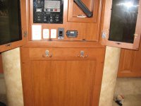
Ok, well mine is actually just to the left side of the UDC, on the other side of the wall, technically in pass through storage. It is on the wall in the pass through storage, on the back side of the UDC wall. I didn't want to put it in there because that's where all the water routes through, and if the hose from the shore hook-ups bursts then it would spray water all on the remote display, and I figured water and electrical stuff mixing wouldn't be a good thing. I'll take a picture when I'm out there next.
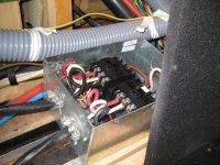
So I got it installed today. I wish that task on no man, lol, but with that said I wouldn't pay $300 for install either. I think the hardest part was connecting the EMS output side with the sensors, there just isn't enough room in there for all that going on and then to bend all those short lengths of 6 gauge wire. Anyhow, I did it all correctly and it all works, the only issue is that the 136 second delay doesn't work. I pulled the little time jumper tab out to set it from 15 to 136 seconds but the "clunk" sound kicks in after 15 seconds still. So like I said, it all works, I just don't have the longer delay if I want it. I called tech support and they seems stumped but said it should be in the circuit board program, so they are sending a new one. I did learn, that unfortunately the remote display is to thick to fit in the switch panel in the living room. I'm totally bummed about that. Here is a picture of the finished install and location. Fits great there and is easily accessible. I used 4 feet of wire for a jumper cable.
View attachment 28892
Looks like a nice installation. I don't know if you did this but when working with the heavy wire it makes it a little easier if you put a loop in the wire just before the connection in the box. Of course that doesn't help much for the leads in the EMS that have the inductive pickup. Also attached a picture of where I mounted my remote display.
So I got it installed today. I wish that task on no man, lol, but with that said I wouldn't pay $300 for install either. I think the hardest part was connecting the EMS output side with the sensors, there just isn't enough room in there for all that going on and then to bend all those short lengths of 6 gauge wire. Anyhow, I did it all correctly and it all works, the only issue is that the 136 second delay doesn't work. I pulled the little time jumper tab out to set it from 15 to 136 seconds but the "clunk" sound kicks in after 15 seconds still. So like I said, it all works, I just don't have the longer delay if I want it. I called tech support and they seems stumped but said it should be in the circuit board program, so they are sending a new one. I did learn, that unfortunately the remote display is to thick to fit in the switch panel in the living room. I'm totally bummed about that. Here is a picture of the finished install and location. Fits great there and is easily accessible. I used 4 feet of wire for a jumper cable.
View attachment 28892

My EMS is set at 136, when you first plug in to shore power you will get nothing for 136 seconds. Then you will hear a clunk from the EMS, the clunk is the contacts closing. After that you will have power to the coach. 136 is probably the safest setting
The transfer switch wait for the generator output to stabilize - about 20 seconds - before it closes the contacts and sends power to the circuit breaker box. In your case, since the EMS is in that path, the 136 second countdown starts after the transfer switch sends power.BTW, the "clunk" happens about 20 seconds after gen start up, no matter the setting, the power doesn't actually start being supplied until 136 seconds AFTER that. It did that on both circuit boards.
Ok, I need some help here because I am in mass confusion. The label on the power hook up (picture below), translates in my electrically stupid mind, that this can handle both 120 and 240 power input. My brother-in-law is helping me get power ready at my parents house so that when we pull it up there for almost 2 weeks of stay that we can power the whole RV. He is pretty electrically smart and has just in case, he showed it to 3 separate electricians and other RV owners, all who say that yes, based on that label you can plug it into 220 (or 240). With that said, Holman Motors told me when I picked it up and did my walk through to NEVER plug it into 220. Obviously I haven't, but I am confused because that label says otherwise. Would you Jedi Masters please help educate me or clarify this? Thank you.
View attachment 28994
The 50 amp 4 pin connector that you normally plug into at an RV park is actually a 220V connection. There are 2 hot wires, each carrying 110V, a neutral, and a ground. When the 2 hot wires get to the circuit breaker box, they power separate busses in the breaker box. Some breakers get power from one 110V buss. Others get power from the other 110V buss. So the 220V coming in is split into two separate 110V lines, each capable of delivering 50 Amps.The label on the power hook up (picture below), translates in my electrically stupid mind, that this can handle both 120 and 240 power input.