Modification: Timer-based DC Circuit Controller
Yesterday, I installed the
ChargeGuard X product from Havis. ChargeGuard works by automatically turning mobile equipment on when you start the engine. When you turn the engine off, the equipment stays on for an adjustable period of time, then is automatically disabled. The ChargeGuard X item I installed also turns equipment off when the battery voltage reaches 10 volts.
My application of this product is for my
BlackVue DR650S-2CH Dash Camera system. The camera will be powered via the Upfitter Switch #5 circuit. The ChargeGuard will continue to power the Dash Camera for the time I've configured. I'm starting with 18 hours. Optionally, I can cut power to the ChargeGuard device be turing Upfitter Switch #5 off.
Install Process
- I determined the best location to mount the ChargeGuard was under the dash and in an area I could easily access without removal, should I need to adjust the timer settings DIP switches
.
- I decided to use an Upfitter Switch (#5) to provide power to the ChargeGuard. This required me to do a few things. 1. I needed to find the blunt cut wiring bundle for the switch circuits and identify the wire I needed. 2. I needed to move adjust a fuse position in the Upfitter Switch Relay Box to convert the switch circuit I wanted to use to "always hot". 3. Determine the best wire routing path from under the dash to the engine compartment.
.
- I wrapped a half-inch of rope over the end of a large screwdriver and taped the rope in place. Then I poked the screwdriver into the large rubber boot under the dash and into the firewall. Using a creeper and a box cutter, I rolled under the truck, felt the screwdriver tip inside the outer boot and slit the boot
.
- I pulled the rope off the screwdriver tip, pulled the rope out about 3 feet and tied it off to a hood support, then went back inside the truck and pulled the screwdriver out of the boot
.
- I placed heavy gauge wire inside some 1/2" split loom, taped the end to the rope and pulled the wire into the cab
.
- I connected the positive lead of my wiring to the blunt cut wire from upfitter switch 5 relay output and connected the negative lead to the battery negative post
.
- Under the dash, I connected the power feed to the ChargeGuard, connected an ATC fuse holder to the output of the ChargeGuard, connected my branch circuit to the output of the fuse holder and the ChargeGuard ground, then used a long tie-wrap to mount the ChargeGuard under the dash
Install Pictures
ChargeGuard-X by Havis
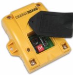
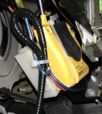
ChargeGuard tie-wrapped under the dash to allow access to timer adjustment DIP switches
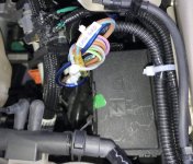
Upfitter Switch Relay Box and Upfitter Switch Circuit Blunt Cut Wires
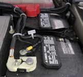
Battery Ground connection for ChargeGuard
Link to complete image gallery.
Link to my truck mod index.

