jbeletti's 2018 Landmark 365 Newport

jbeletti

Well-known member
Byrd - I remember the day, sometime last year where I was running some wires and noticed this wall space between the propane door and the storage bay door. I took a picture of it and texted it to the plant manager. He said in the front bathroom models, it's a plumbing chase. Sure enough, lots of plumbing in there.

Then I heard from Jerrod J that he saw a Newport out in Cali where a guy had opened his up. Then I saw Paul A's mod on his Newport. I had to do it!
 

jbeletti

Well-known member
MOD: Add second water pump to increase flow rate in coach

FLOW RATE TESTING HAS BEEN COMPLETED AND LOGGED BELOW - FOLLOW-UP ITEMS HAVE BEEN ADDED TO THE TO DO LIST BELOW

As many know, we filter our our water fairly extensively as it enter the coach, then we produce Reverse Osmosis water for 100% of our water needs (cooking, drinking, cleaning, showering etc.). As we rely entirely on this stored water, we need a robust demand pumping system. Ken and Kathy Adams are staying in our RV pad for a while. Ken is assisting with this project.

GOAL
  • Significantly increase water flow to fixtures
I'll update this post as the project moves forward.

BILL OF MATERIALS
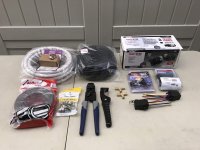
  • 1 ea Remco 54REBELJRV Water Pump (4.0 GPM)
  • 1 ea ShurFlo Strainer
  • 12 ea 1/2" PEX Pinch Clamps
  • 2 ea Barbed PEX Tees
  • 2 ea 5-pin Bosch Style SPDT 12V DC 40A/30A waterproof automotive relay
  • 20 ft 1/2" Split Loom Tubing
  • 6 ft Sierra International Clear White PVC Tubing Polyester Reinforced (Blue-Tracer) 1/2"
  • 40 ft 10 gauge Red/Black Zip Wire
  • Misc electrical fittings (mostly heat shrinkable butt splices), tie-wraps etc.
PROJECT COST
~$230

To Do Work List
  • Perform additional testing to determine under what conditions the second pump will activate
  • Contact Remco with some questions:
    1. Should we have seen a larger incremental gain in flow rate with the addition of the
    second pump?
    2. Should we adjust the pressure switch in the second pump to have it activate at a lower
    pressure rate?
    3. Could the higher flow rate of pump one be putting pressure on the output of pump two
    through the tee? If yes, should we add an inline check valve on pump two side of the tee?
PROGRESS (reverse chrono)
5-July-2018
  • Retested water flow rate at same 3 points in coach and compare results to baseline values
  • Updated project paper with test results, observations and conclusion
Microsoft WordScreenSnapz011.jpg

4-July-2018
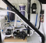
  • Reinstalled into water plant bay, board containing the 3 water pumps
  • Plumbed Demand Water Pumps inlet and outlet to coach water system
  • Pulled Demand Pump power feeds inside 1/2" split loom tubing to battery area
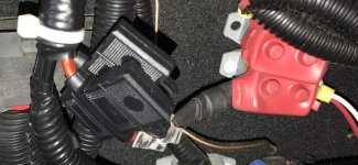
  • Connected high-current inline fuse holders to power feeds in battery bay and connected via ring terminal to mini breaker copper buss bar
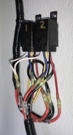
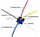
  • Wire power feeds into Relays
  • Connected power feed grounds to ring terminal and to existing lug on frame in battery bay
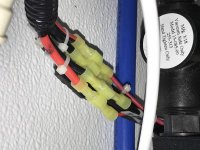
  • Connected power feeds to waterproof heavy duty relays in water plant bay
  • Connected existing water pump power line to both relays to use as DC trigger
  • Powered up water pumps to:
    - Check electrical operation - passed
    - Check for pump prime - passed
    - Perform leak test - passed
IMG_8647.jpg IMG_8646 2.jpg IMG_8648.jpg IMG_8645.jpg IMG_8651.jpg Relay Wire Designations and AWG.jpg

29-June-2018
  • Performed and recorded water flow rate at 3 points in coach:
    - Kitchen sink: nnn GPM
    - Bathroom shower: nnn GPM
    - Outdoor Shower: nnn GPM
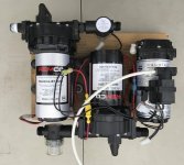
  • Removed board holding existing RO Boost Pump and Demand Pump #1
  • Relocated existing pumps on board in order to make room for and mounted Demand Pump #2
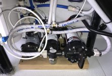
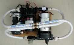
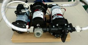
  • Plumbed Water Inlets (Suction) of both Demand Pumps together using a barbed brass T and vinyl hose
  • Plumbed Water Outlets (Pressure) of both Demand Pumps together using a barbed brass T and vinyl hose
  • Mounted 2 high-current, waterproof Relays (to power both Demand Pumps)
  • Ran 2 sets of 10 gauge wire from battery / DC breakers area in front (Generator) cabinet to Relays in water pump area for the 2 Demand Pumps
IMG_8595.jpg IMG_8597.jpg Pumps - Plumbed on Bench - 01.jpg Pumps - Plumbed on Bench - 02.jpg
 
Last edited:

jbeletti

Well-known member
MOD: Exterior Inverter Status Light

As I've done in a couple of my past coaches as well as a few pal's coaches, today, I added an exterior Inverter Status light. This is a simple project that for some with residential refrigerators, provides some value as 'peace of mind'. Ken and Kathy Adams are staying in our RV pad for a while. Ken assisted with this project.

Sometime back, I documented this project. I've attached a PDF of this project to this post.

GOAL
  • While traveling, have the ability to know that the Inverter is still on and the likelihood of the Residential Refrigerator being on is very high.
BILL OF MATERIALS
  • 1 ea Green LED light
  • 1 ea 120 VAC to 12 VDC power pack (wall wart) - 1 amp
  • 8 ft 16 gauge wire pair
  • Misc electrical fittings (mostly butt splices and tie-wraps etc.)
PROJECT COST
~$14

PROGRESS (reverse chrono)
Project is complete - time spent is about 30 minutes

29-June-2018
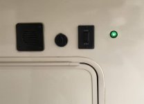
  • Using 3/4" Forstner bit, drilled hole in front wall of coach to the right of the front jack switch
  • Cut off plug and all but 1 foot of wire from power pack (retained plug with original cable for future projects)
  • Spliced about 8 feet of 16 gauge wire onto LED light using butt splices
  • Place 16 gauge wire in 1/4" split loom tubing and taped ends onto wire
  • Passed light wire through hole drilled in step above and pushed LED light in supplied grommet, then into hole
  • Routed wiring in battery bay area and secured with tie-wraps
  • Spliced power pack to wire from LED using butt splices
  • Plugged power pack into unused outlet on duplex GFI outlet of inverter
  • Noted green LED as lit - smiled - moved onto next project

IMG_8600.jpg
 

Attachments

  • RV_Project_–_Inverter_Status_Light.pdf
    247.7 KB · Views: 44

Jesstruckn/Jesstalkn

Well-known member
Re: MOD: Add second water pump to increase flow rate in coach

THIS MOD IS IN PROGRESS. WAITING ON ADDITIONAL SUPPLIES. EXPECTED TO COMPLETE MONDAY, JULY 2.

As many know, we filter our our water fairly extensively as it enter the coach, then we produce Reverse Osmosis water for 100% of our water needs (cooking, drinking, cleaning, showering etc.). As we rely entirely on this stored water, we need a robust demand pumping system. Ken and Kathy Adams are staying in our RV pad for a while. Ken is assisting with this project.

GOAL
  • Significantly increase water flow to fixtures
I'll update this post as the project moves forward.

BILL OF MATERIALS
  • 1 ea Remco 54REBELJRV Water Pump (4.0 GPM)
  • 1 ea ShurFlo Strainer
  • 12 ea 1/2" PEX Pinch Clamps
  • 2 ea Barbed PEX Tees
  • 2 ea 5-pin Bosch Style SPDT 12V DC 40A/30A waterproof automotive relay
  • 20 ft 1/2" Split Loom Tubing
  • 6 ft Sierra International Clear White PVC Tubing Polyester Reinforced (Blue-Tracer) 1/2"
  • 40 ft 10 gauge Red/Black Zip Wire
  • Misc electrical fittings (mostly heat shrinkable butt splices), tie-wraps etc.
PROJECT COST
~$230

To Do Work List
  • Put both Demand Pump power feeds inside 1/2" split loom tubing
  • Wire power feeds into Relays
  • Add high-current inline fuse holders to power feeds
  • Connectorize DC + lines on both power feed and connect to buss bar side of DC breakers
  • Connectorize DC - lines on both power feed and connect to suitable ground in battery bay area
  • Connect existing water pump power line to both relays as DC trigger
  • Reinstall board containing the 3 water pumps
  • Plumb Demand Water Pumps Inlet and outlet to coach water system
  • Connect power leads of both Demand Pumps to the outputs of their respective relays
  • Power and pressure test system
  • Retest water flow rate at same 3 points in coach and compare results to baseline values
PROGRESS (reverse chrono)

29-June-2018
  • Performed and recorded water flow rate at 3 points in coach:
    - Kitchen sink: nnn GPM
    - Bathroom shower: nnn GPM
    - Outdoor Shower: nnn GPM
  • Removed board holding existing RO Boost Pump and Demand Pump #1
  • Relocated existing pumps on board in order to make room for and mounted Demand Pump #2
  • Plumbed Water Inlets (Suction) of both Demand Pumps together using a barbed brass T and vinyl hose
  • Plumbed Water Outlets (Pressure) of both Demand Pumps together using a barbed brass T and vinyl hose
  • Mounted 2 high-current, waterproof Relays (to power both Demand Pumps)
  • Ran 2 sets of 10 gauge wire from battery / DC breakers area in front (Generator) cabinet to Relays in water pump area for the 2 Demand Pumps
View attachment 58343 View attachment 58344 View attachment 58347 View attachment 58348
Jim your going to be able to pressure wash your rig with that setup.. LOL
Looking good.
Qhat kind of pressure are you looking for ?? Are you concerned with causing leaks in the system ?

Sent from my SM-N950U using Tapatalk
 

jbeletti

Well-known member
Re: MOD: Add second water pump to increase flow rate in coach

Jim your going to be able to pressure wash your rig with that setup.. LOL
Looking good.
Qhat kind of pressure are you looking for ?? Are you concerned with causing leaks in the system ?

Sent from my SM-N950U using Tapatalk

Jerrod - I'm shooting to nearly double my flow rate at the fixtures. I don't have a PSI goal and took no PSI baseline measurements. With the way the pumps work, I don't think we're significantly raise PSI. At least nothing in the danger zone.

I haven't brought my flow rate measurements in the house to add them to Mod post but indoors, no fixture was greater than 1 GPM and most were .5 GPM. So - usable, but not great.
 

jbeletti

Well-known member
FEATURE ADDITION: SureCall Fusion2Go 3.0 RV Voice, Text & 4G LTE Cell Phone Signal Booster for Recreational Vehicle

BASELINE TESTING AND PRODUCT PERFORMANCE TESTING IS COMING AND WILL BE ADDED HERE SOON.

A few months ago, fellow Heartlander, Michael Barnett asked me about Cellular Boosters, what I knew about them etc. Several years ago, I used a Wilson (3G) Cellular Booster with short external antenna and interior patch-style antenna. My results with it were marginal.

Michael piqued my curiosity for this product so I set out to look for reviews and technical data for the booster Michael was favoring - the
SureCall Fusion2Go 3.0 RV Voice, Text & 4G LTE Cell Phone Signal Booster for Recreational Vehicles. The independent reviews I found were mostly comparing the SureCall product with the Wilson WeBoost product. In every case, SureCall was the winner.

I contacted an industry acquaintance (WPS Antennas) who has supported some of my telecommunication projects over the years. In cooperation with SureCall, an evaluation Fusion2Go 3.0 RV Voice, Text & 4G LTE Cell Phone Signal Booster for Recreational Vehicles was sent to me. I finally got it installed. Ken and Kathy Adams are staying in our RV pad for a while. Ken assisted with this project.

GOAL
  • While traveling, especially in locations where Verizon signal inside the coach was marginal, have the ability to pick up a stronger signal from an exterior rooftop antenna and boost that signal inside the RV in an effort to increase voice call availability and improve cellular data speeds.
BILL OF MATERIALS
  • 1 ea SureCall Fusion2Go 3.0 RV Voice, Text & 4G LTE Cell Phone Signal Booster for Recreational Vehicles
  • 1 ea 4"x4" plastic electrical box and lid with integrated rubber gasket
  • 1 ea Compression-style entrance connector (for antenna coax to enter electrical box
  • Misc supplies (rubber tape, electrical tape, pink string, white silicone rubber, screws, electrical terminals, 1/4" split loom tubing)
PROJECT COST
~$5 for supplies (device was sponsored)

PROGRESS (reverse chrono)
Project is 90% complete - time spent to date is about 6 hours

30-June-2018
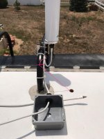
  • I previously mounted outdoor antenna to rear ladder
  • Using fiberglass wire pulling rods, fished pink string through door side air conditioning duct (note: we first spent over an hour trying to fish from ceiling light to light but had a difficult time getting through roof trusses)
  • Cut hole in ceiling of rear cap overhead cabinet to fish one end of pink string out of AC duct
  • Fished pink string out of AC duct near mid-coach, then fished across ceiling to above coat closet, then out an existing hole in closet ceiling
  • Attached antenna coax N connector to antenna, sealed connector with rubber tape and secured with tie-wrap. Tie-wrapped coax to ladder.
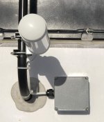
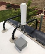
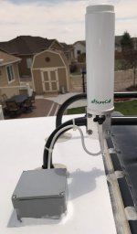
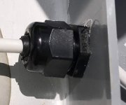
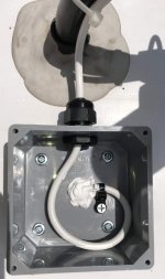
  • Added compression-style entrance connector to 4"x4" electrical box and drilled exit hole in bottom of box
  • Using 3/4" Forstner bit, drilled hole in fiberglass roof material and down into attic space above rear cap upper cabinet
  • Covered bottom of electrical box with white silicone rubber (I was out of Dicor Lap Sealant), aligned hole in box with hole in roof and screwed box to roof, then sealed outside perimeter of box to roof
  • Using a single 3' section of wire push rod with 5 foot of pink string attached, fished rod through hole in box/roof and out hole in rear cap upper cabinet ceiling, then tied string off to ladder
  • Tied, then taped pink string to booster end of antenna coax, then pulled all coax into rear cap upper cabinet
  • Made a small coil of coax inside electrical box on roof, then fastened coil down to inside-bottom of box with tie-wrap and a screw
  • Added lid to box
  • Attached coax to previously run pink string in AC duct and pulled coax all the way to midpoint of coach and into upper shelf of coat closet
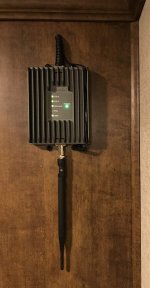
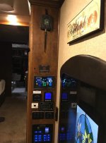
  • Determined mounting location for SureCall device in the upper foot of the sidewall of the coat closet that has all the coach switches etc. and drilled hole on wall for coax and power to come out
  • Fished coax and power cable out from closet to device mounting location
  • Connected coax and power cable to SureCall device, then mounted device to wall using 4 screws
  • Cut off cigarette lighter plug from power cable and added electrical terminals to cable ends
  • Connected power cable to 6 position fuse block in closet, then added fuse
  • Replaced all removed ceiling lighting and AC grills
TO DO LIST
  • Devise method to, then implement a block past the last air conditioning output duct as we blew the end out with our wire pushing rods (oops!)
  • With booster off, establish baseline metrics (RSSI, Data Speed tests, number of bars etc.)
  • Retest all metrics with booster on to determine performance to baseline
IMG_8634 2.jpg IMG_8632 2.jpg IMG_8619.jpg IMG_8616.jpg IMG_8614.jpg IMG_8610.jpg IMG_8608.jpg IMG_8607.jpg IMG_8602.jpg IMG_8601.jpg
 
Last edited:

esscobra

Well-known member
Wilson has a new rv model out with pole that can be raised - just got 1 in today - I sell lots of Wilson units and cradlepoint cellular routers for remote homes/businesses and jobsite trailers- hope to get tested/installed in remote jobsite this week
 

porthole

Retired
Wilson has a new rv model out with pole that can be raised - just got 1 in today - I sell lots of Wilson units and cradlepoint cellular routers for remote homes/businesses and jobsite trailers- hope to get tested/installed in remote jobsite this week

Be curious to see what you come up with and think about it.

I was just trying to access my WiFi ranger router this morning and am about ready to throw it in the horse paddock behind me. What a frustrating piece of equipment.

I still haven’t run my cellular antenna to the roof and am waiting to see what is the latest and greatest and hopefully do it ‘one time’
 

jbeletti

Well-known member
Wilson has a new rv model out with pole that can be raised - just got 1 in today - I sell lots of Wilson units and cradlepoint cellular routers for remote homes/businesses and jobsite trailers- hope to get tested/installed in remote jobsite this week

That's cool. If you don't mind, consider sending me your test procedure for determining the incremental improvement over no booster. I am just making up my own test procedures but would like to do something a bit more scientific.

For my install, as I am never setup long-term anywhere, I am not a candidate for a directional antenna as I'd never want to deploy, peak and lock it down every few days :) I may consider a much higher gain omni-directional antenna on a motorized base down the road.
 

esscobra

Well-known member
so I do lots of the install in homes and construction trailers - I will try and get a base with and without using my bighorn - the directional 98% of the time is the best- even without a signal meter - the new unit is geared for weekenders and semi permanent - as the mast raises and lowers and can be stowed - ill open it up and get some pics up and away from the rv will improve signal
 

Oldelevatorman

Well-known member
Re: MOD: Exterior Inverter Status Light

As I've done in a couple of my past coaches as well as a few pal's coaches, today, I added an exterior Inverter Status light. This is a simple project that for some with residential refrigerators, provides some value as 'peace of mind'. Ken and Kathy Adams are staying in our RV pad for a while. Ken assisted with this project.

Sometime back, I documented this project. I've attached a PDF of this project to this post.

GOAL
  • While traveling, have the ability to know that the Inverter is still on and the likelihood of the Residential Refrigerator being on is very high.
BILL OF MATERIALS
  • 1 ea Green LED light
  • 1 ea 120 VAC to 12 VDC power pack (wall wart) - 1 amp
  • 8 ft 16 gauge wire pair
  • Misc electrical fittings (mostly butt splices and tie-wraps etc.)
PROJECT COST
~$14

PROGRESS (reverse chrono)
Project is complete - time spent is about 30 minutes

29-June-2018
  • Using 3/4" Forstner bit, drilled hole in front wall of coach to the right of the front jack switch
  • Cut off plug and all but 1 foot of wire from power pack (retained plug with original cable for future projects)
  • Spliced about 8 feet of 16 gauge wire onto LED light using butt splices
  • Place 16 gauge wire in 1/4" split loom tubing and taped ends onto wire
  • Passed light wire through hole drilled in step above and pushed LED light in supplied grommet, then into hole
  • Routed wiring in battery bay area and secured with tie-wraps
  • Spliced power pack to wire from LED using butt splices
  • Plugged power pack into unused outlet on duplex GFI outlet of inverter
  • Noted green LED as lit - smiled - moved onto next project

View attachment 58345

Jim, where did you buy the power pack? I haven't been able to locate one.


Sent from my iPhone using Tapatalk
 

jbeletti

Well-known member
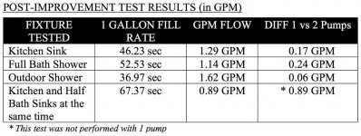
Flow Rate testing of the Parallel Water Pumps installation has been completed. A table (image) has been added to post 102 below under progress for 5-July-2018.

At this time, I can say this was a small amount of money and a lot of effort for very little gain. Something is wrong. More questions and testing lay ahead.
 

danemayer

Well-known member
Jim,

Have you considered running the pumps in series as a way to increase water pressure? I don't know if that would work, but maybe that would be a reasonable experiment.
 

CDN

B and B
Jim,
I am sitting in our favourite park with 3G. Looking to hear on your experience with Sure Call system. I have seen some Wilson/ Weboost systems with less than ideal results. I like the ceiling vent pull for the coax.

Brian
 
Top