jbeletti's 2018 Landmark 365 Newport

jbeletti

Well-known member
MOD: Air Conditioning Volume Reduction in Half Bathroom

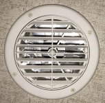
Anyone with a Landmark Newport may agree that you can hang meat in the half bath. It's a small room and the single air conditioning outlet in there is only a couple of feet away from the air conditioner unit. So the flow into that small space is huge!

I removed the grill, reflashed the gap between the ceiling panel and the bottom of the AC plenum, then I used a piece of heavy paper and foil tape to make a cover with a much smaller hole in it to reduce the air flow into the room. It worked!

Time will tell if I've reduced it too much but the first couple of hours are encouraging.

Here's a picture of the finished product:
IMG_9342.jpg

Here's a link to all the pictures I took during the project.
 

Terry H

Past Texas North Chapter Leader/Moderator
Staff member
My guess is the half bath could have been used as backup refrig.
 

Bones

Well-known member
MOD: Air Conditioning Volume Reduction in Half Bathroom

Anyone with a Landmark Newport may agree that you can hang meat in the half bath. It's a small room and the single air conditioning outlet in there is only a couple of feet away from the air conditioner unit. So the flow into that small space is huge!

I removed the grill, reflashed the gap between the ceiling panel and the bottom of the AC plenum, then I used a piece of heavy paper and foil tape to make a cover with a much smaller hole in it to reduce the air flow into the room. It worked!

Time will tell if I've reduced it too much but the first couple of hours are encouraging.

Here's a picture of the finished product:
View attachment 59092

Here's a link to all the pictures I took during the project.
Your half bath is cold in the summer and ours is an oven in the winter. :) I think I would have cheated and bought a louvered vent. LoL. Looks good Jim.
 

jbeletti

Well-known member
For anyone interested in this magazine rack directly from Heartland, order as follows:
  1. Call 877-262-8032 and ask for Parts
  2. Order Heartland P/N 0168366 - retail cost $25.50 (as of 20-Aug-2018)
  3. If you are a Heartland Owners Club member, advise the parts person and ask for a 10% discount
 

jbeletti

Well-known member
UPGRADE: Installed Separate Furnace Thermostat

ABSTRACT
In many of our RVs, our Suburban or Atwood furnace is managed by a unified thermostat, usually Dometic. This has been the case in all 7 of my 8 Landmarks with a Suburban furnace and Dometic air conditioners.

The Suburban furnace used in my Landmark has a +12 vdc output wire (blue) that is run to a my rearmost air conditioner control board up on the roof. When the Dometic thermostat mode is set to Furnace and when it calls for heat based on it’s set point versus the current temperature, the relay in the control board in the AC unit closes and returns the +12 vdc signal to the furnace (a second blue wire at the furnace). For the duration the furnace receives +12 vdc on this return line, it runs and continues to run until that circuit is opened (via the AC unit relay).

That all to say that recently, my rearmost AC unit has had the control board burn up (sort of - smoldered wiring in the metal electrical box to be exact). As such, if needed, I couldn't use my furnace until AC unit repairs / replacement were completed. To resolve the lack of furnace control and improve the situation going forward, I have installed a separate thermostat to control my “furnace only”.

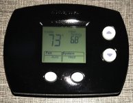
I selected the Honeywell FocusPro 5000 (TH5110D1006). I'm powering it via 2 AAA batteries inside the thermostat. Of all the connection terminals on the thermostat, I’m using only two:
Rc/R and W. The +12 vdc from the furnace will be connected to R and the return line from the furnace will be connected to W.

OPERATIONAL THEORY TESTING
  1. I disconnected the coach (blue and green) wiring from the 2 blue wires coming from the furnace, then I shorted those 2 wires and the furnace ran. I opened those 2 wires and the furnace stopped running.
  2. On the new thermostat, with it set to Heat and with a set point lower than the current temperature, using an ohmmeter, I measured resistance between the R and W connections and it had infinite resistance - an open circuit. I then changed the heat set point to a setting higher than the current temperature and remeasured resistance across R and W. I audibly heard a click (the thermostat relay closing) and I measured zero resistance - a short or closed circuit.
GOAL
  • Be able to operate the furnace via a thermostat and control system independent of the air conditioner unit
BILL OF MATERIALS
PROJECT COST
~$50

PROGRESS
Project is complete - time spent is about 2 hours

21-August-2018
  • Used a VOM to test thermostat to determine suitability (see testing detail above)
  • Disconnected two furnace Blue wires and tested them to determine proof of concept (see testing detail above)
  • Disassembled new thermostat, painted it black and reassembled
  • Ran new section of 2 conductor wire from furnace to thermostat area on interior wall near bedroom steps
  • Connected furnace Blue (12 vdc) wire to R terminal on new thermostat
  • Connected furnace Blue (return) wire to W terminal on new thermostat
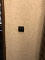
  • Mounted new thermostat on wall above 2 existing AC thermostats
  • Connected two furnace Blue wires to new thermostat wiring
  • Tested operation
IMG_9370.jpg
 

Bones

Well-known member
UPGRADE: Installed Separate Furnace Thermostat

ABSTRACT
In many of our RVs, our Suburban or Atwood furnace is managed by a unified thermostat, usually Dometic. This has been the case in all 7 of my 8 Landmarks with a Suburban furnace and Dometic air conditioners.

The Suburban furnace used in my Landmark has a +12 vdc output wire (blue) that is run to a my rearmost air conditioner control board up on the roof. When the Dometic thermostat mode is set to Furnace and when it calls for heat based on it’s set point versus the current temperature, the relay in the control board in the AC unit closes and returns the +12 vdc signal to the furnace (a second blue wire at the furnace). For the duration the furnace receives +12 vdc on this return line, it runs and continues to run until that circuit is opened (via the AC unit relay).

That all to say that recently, my rearmost AC unit has had the control board burn up (sort of - smoldered wiring in the metal electrical box to be exact). As such, if needed, I couldn't use my furnace until AC unit repairs / replacement were completed. To resolve the lack of furnace control and improve the situation going forward, I have installed a separate thermostat to control my “furnace only”.

I selected the Honeywell FocusPro 5000 (TH5110D1006). I'm powering it via 2 AAA batteries inside the thermostat. Of all the connection terminals on the thermostat, I’m using only two:
Rc/R and W. The +12 vdc from the furnace will be connected to R and the return line from the furnace will be connected to W.

OPERATIONAL THEORY TESTING
  1. I disconnected the coach (blue and green) wiring from the 2 blue wires coming from the furnace, then I shorted those 2 wires and the furnace ran. I opened those 2 wires and the furnace stopped running.
  2. On the new thermostat, with it set to Heat and with a set point lower than the current temperature, using an ohmmeter, I measured resistance between the R and W connections and it had infinite resistance - an open circuit. I then changed the heat set point to a setting higher than the current temperature and remeasured resistance across R and W. I audibly heard a click (the thermostat relay closing) and I measured zero resistance - a short or closed circuit.
GOAL
  • Be able to operate the furnace via a thermostat and control system independent of the air conditioner unit
BILL OF MATERIALS
PROJECT COST
~$50

PROGRESS
Project is complete - time spent is about 2 hours

21-August-2018
  • Used a VOM to test thermostat to determine suitability (see testing detail above)
  • Disconnected two furnace Blue wires and tested them to determine proof of concept (see testing detail above)
  • Disassembled new thermostat, painted it black and reassembled
  • Ran new section of 2 conductor wire from furnace to thermostat area on interior wall near bedroom steps
  • Connected furnace Blue (12 vdc) wire to R terminal on new thermostat
  • Connected furnace Blue (return) wire to W terminal on new thermostat
  • Mounted new thermostat on wall above 2 existing AC thermostats
  • Connected two furnace Blue wires to new thermostat wiring
  • Tested operation
View attachment 59102
nice. Are you going to leave it that way when the AC is repaired?
 

jbeletti

Well-known member
nice. Are you going to leave it that way when the AC is repaired?

Hi Dave - the AC has been replaced. I wrote the article many weeks ago and may have missed changing it to reflect that the AC is now good to go.

That said, yes, I plan to leave the separate thermostat for the furnace. Technically, I could parallel that thermostat with the AC control to use either, but no need to make it more complicated, so I just tied off the wire pair that came down from the AC unit.

Real early this morning, it got cold enough in here for the furnace to run and it worked well. Woot!
 

ksucats

Well-known member
Jim: So what I'm hearing from your post is that the furnace is dictated by the circuitry in the back AC. If it isn't working then the furnace doesn't work either???

Have been having problems with our rear AC - Dan and everyone have been super in providing ideas and areas to check but so far no joy (see https://heartlandowners.org/showthread.php/72764-AC-Won-t-run-on-30-Amps ). Now this has given me something else to be concerned about. Have not tried the furnace.

/s/ Ron
 
Last edited:

jbeletti

Well-known member
MOD: Relocated Half Bath Light Switches

ABSTRACT
In the Landmark Newport floor plan, in the lower level half bath, there are 2 lighting circuits. There is a 2-gang switch near the sink in the half bath that controls these 2 lighting circuits. In my opinion, the way we use this room, the switches are not ideally located.

GOAL

  • Be able to operate the half bath lighting from conveniently located switches on the wall, to the left as you enter the room.
BILL OF MATERIALS
PROJECT COST
~$20

PROGRESS
Project is complete - time spent is about 2 hours

24-August-2018
  • Determine best placement for switch and cut hole in wall to fit new double-switch
  • Run 4-conductor wire from new switch to under sink area of vanity*
  • Remove original switch from wall
  • Drill hole in wall under sink, below original switch location
  • Fish 4-conductor wire up to original switch location
  • Terminate wires at new switch with female terminals, connect to switches and install switch and plate to wall
  • Use tie-wraps with screw holes and screws to manage wire inside vanity cabinet
  • Terminate wires at original switch location with male terminals
  • Disconnect lighting circuit wire terminals from original switch and connect them to wiring from the new switch
  • Test new switches for proper operation
  • Reinstall original switch with no wires connected to it**
  • Clean up work area, take pictures, drink beer :)
* I installed the new switch many months ago and shoved the wiring inside the wall. Recently, at a service center, while they had that wall open, I had them run the wire to inside the vanity cabinet of the half bath

** One day, I may replace the unused wall switch with either a blank plate or remove the switches from their plate and replace them with switch blanks

Half-Bath_Light_Switch_Relocation_01 (1).jpg

Link to gallery of installation images
 

jbeletti

Well-known member
MOD: Pantry Door Enhancement - added Push Button Latch

ABSTRACT
In the Landmark Newport floor plan, like several others, it has a floor to ceiling pantry in the kitchen that has a full-length cabinet door. The pantry has several drawers on full-extension drawer glides. With drawers that are heavily loaded, they can have a tendency to roll outward while traveling and bang into the inside of the pantry door. We have installed travel latches on each of the pantry drawers - but sometimes we forget to lock them. Recently, we had a super-heavily loaded drawer bang the pantry door open and the drawer shot all the way out! It bent and twisted the drawer glides and spilled ball bearings all over the place.

GOAL

  • Have an additional latch for the pantry door to hold it in place better that the catches in use now.
BILL OF MATERIALS
PROJECT COST
~$5

PROGRESS
Project is complete - time spent is about a half hour

6-September-2018
  • Determine and layout where to drill 1" hole in pantry door
  • Using 1" Forstner bit, drill hole in pantry door
  • Install new latch in door
  • Determine and layout where to install the catch for the cam of the new latch
  • Install wood block behind vertical cabinet stile for reinforcement
  • Install catch
  • Test latch / catch fitment / operation
  • Adjust (file) catch for smooth operation when closing cabinet door with latch cam retracted
  • Clean up work area, take pictures, drink beer :) Actually, it was too early for beer :)

Friend, Heartlander and Neighbor, Gregg W assisted with this project.

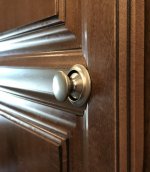
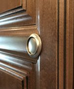
Below are two images of the completed project, one showing the button out (unlatched - cam retracted) and one showing the button in (latched - cam extended and held by catch)

IMG_9473.jpg IMG_9474.jpg

Link to gallery of installation images
 

Bones

Well-known member
MOD: Pantry Door Enhancement - added Push Button Latch

ABSTRACT
In the Landmark Newport floor plan, like several others, it has a floor to ceiling pantry in the kitchen that has a full-length cabinet door. The pantry has several drawers on full-extension drawer glides. With drawers that are heavily loaded, they can have a tendency to roll outward while traveling and bang into the inside of the pantry door. We have installed travel latches on each of the pantry drawers - but sometimes we forget to lock them. Recently, we had a super-heavily loaded drawer bang the pantry door open and the drawer shot all the way out! It bent and twisted the drawer glides and spilled ball bearings all over the place.

GOAL

  • Have an additional latch for the pantry door to hold it in place better that the catches in use now.
BILL OF MATERIALS
PROJECT COST
~$5

PROGRESS
Project is complete - time spent is about a half hour

6-September-2018
  • Determine and layout where to drill 1" hole in pantry door
  • Using 1" Forstner bit, drill hole in pantry door
  • Install new latch in door
  • Determine and layout where to install the catch for the cam of the new latch
  • Install wood block behind vertical cabinet stile for reinforcement
  • Install catch
  • Test latch / catch fitment / operation
  • Adjust (file) catch for smooth operation when closing cabinet door with latch cam retracted
  • Clean up work area, take pictures, drink beer :) Actually, it was too early for beer :)

Friend, Heartlander and Neighbor, Gregg W assisted with this project.

Below are two images of the completed project, one showing the button out (unlatched - cam retracted) and one showing the button in (latched - cam extended and held by catch)

View attachment 59327 View attachment 59328

Link to gallery of installation images

Your last few mods have been great to read Jim. Keep up the awesome work.
 

klindgren

Retired Virginia Chapter Leaders
MOD: Pantry Door Enhancement - added Push Button Latch

ABSTRACT
In the Landmark Newport floor plan, like several others, it has a floor to ceiling pantry in the kitchen that has a full-length cabinet door. The pantry has several drawers on full-extension drawer glides. With drawers that are heavily loaded, they can have a tendency to roll outward while traveling and bang into the inside of the pantry door. We have installed travel latches on each of the pantry drawers - but sometimes we forget to lock them. Recently, we had a super-heavily loaded drawer bang the pantry door open and the drawer shot all the way out! It bent and twisted the drawer glides and spilled ball bearings all over the place.

GOAL

  • Have an additional latch for the pantry door to hold it in place better that the catches in use now.
BILL OF MATERIALS
PROJECT COST
~$5

PROGRESS
Project is complete - time spent is about a half hour

6-September-2018
  • Determine and layout where to drill 1" hole in pantry door
  • Using 1" Forstner bit, drill hole in pantry door
  • Install new latch in door
  • Determine and layout where to install the catch for the cam of the new latch
  • Install wood block behind vertical cabinet stile for reinforcement
  • Install catch
  • Test latch / catch fitment / operation
  • Adjust (file) catch for smooth operation when closing cabinet door with latch cam retracted
  • Clean up work area, take pictures, drink beer :) Actually, it was too early for beer :)

Friend, Heartlander and Neighbor, Gregg W assisted with this project.

Below are two images of the completed project, one showing the button out (unlatched - cam retracted) and one showing the button in (latched - cam extended and held by catch)

View attachment 59327 View attachment 59328

Link to gallery of installation images

Jim, do you think this mod would work on the washer/dryer door? The original two latches Heartland installed on that door keep breaking and I am looking for a way to latch the door that doesn't involve replacing a latch every couple of months.
 

jbeletti

Well-known member
Jim, do you think this mod would work on the washer/dryer door? The original two latches Heartland installed on that door keep breaking and I am looking for a way to latch the door that doesn't involve replacing a latch every couple of months.

Keith,

These latches could likely work on most any door or drawer. The trickiness comes in on the door or drawer front style vs. the backset required for these latches. You can see from my installation that the style of the door vs the location I needed to install the latch, isn't ideal - though it works.

I'm wondering why your latches are breaking. Seems odd to me unless your W/D is tipping forward and into the closed door while traveling. If so, a single alternate style latch may not hold that situation back.
 

bwdt

Well-known member
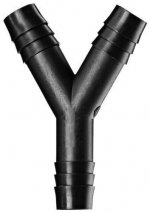
I was just looking at your water pump system and noticed something that you could do that would help your flow. You are using a T connector instead of a Y connector. The T connectors have a lot of restriction to flow and a Y connector would reduce restriction substantially.
 

jbeletti

Well-known member
I was just looking at your water pump system and noticed something that you could do that would help your flow. You are using a T connector instead of a Y connector. The T connectors have a lot of restriction to flow and a Y connector would reduce restriction substantially.
I had trouble sourcing a 1/2" WYE. Let me know if you see any. Ideally, it would have 1/2" barb fittings as well.

On edit: May have found some (link)
s-l500.jpg
 
Top