My Mods: Water Pump Switch Project
Update for 6-Apr-2016
It's been over 5 months since I installed the 3 additional water pump switches. And they've worked well - very handy.
Well, today I finally added the 4th and final switch (kitchen) and connected the Pump Status LED on the front of the coach.
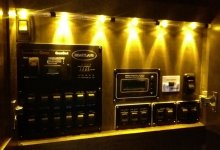
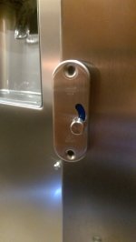
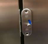
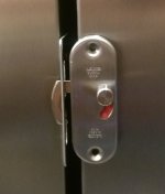
Water Pump Circuit ON
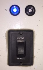
Water Pump and Refer Inverter Circuits both ON
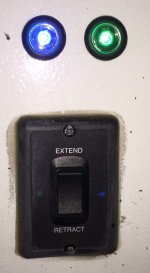
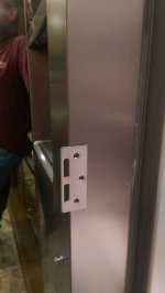
Kitchen Water Pump Switch Installed (sorry for the blur)
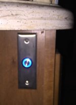 Update for 24-Oct-2015
Today was "the day"! Today I installed the previously built water pump switch circuit and pulled 3 of the 4 wiring harnesses needed for my 4 switch locations. I also completed the installation of the first 3 switches. AND IT WORKS!
I installed the Water Pump Status LED (blue) on the front of the RV. Noticed it's inop

Easy troubleshoot tomorrow.
Here's a link to the entire image gallery for this project and below are a few of the pictures.
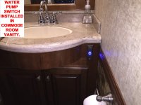
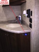 Video of switch in action <CLICK IMAGE BELOW)

--------------------------------
In our LM365, there are two water pump switches. These switches are SPDT type used to make a 3-way circuit to turn the water pump on or off from two locations. Landmark 365 comes with one switch outside on the off-door side inside the UDC (universal docking center) and another switch inside the coach in the switch panel with all the other switches.
I want to install switches where they are even more convenient for those times when we are boondocking (a couple times a year) and every day we travel.
The system I've devised will have 5 switches as follows:
- UDC
- Kitchen Sink area
- Bedroom Sink area
- Commode Room Sink area
- Switch Panel area
At it's heart, the project uses a
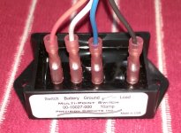
Precision Circuits "Water Pump Relay". This relay is what is referred to by some as a ground switch. Reason being is that when a switch lead on the relay is momentarily grounded, it latches or unlatches the relay. I ordered the relay on
eBay ($42).
I also wanted a visible indicator that the water pump circuit is on, so I sourced momentary switches with a built-in light. My first order (via aliexpress.com and shipped from China) was a bust. I didn't realize the switches didn't have a dropping resistor built-in and I burned out the LEDs. Oops! Also, the electrical contacts were teeny and I'd have to solder everything. I'm quite capable in this area but my old eyes and fat fingers wouldn't have liked it.
Round 2 of
switches were ordered via eBay ($8 ea delivered) and shipped from China (though also available from the same seller on aliexpress.com). The new switches I selected were better for me in these ways:
- Larger diameter - easier to fit a finger tip in the center to activate
- Built-in dropping resistor (no soldering - ya!)
- Supplied with an automotive-style socket with 6" leads (ya again - no soldering!)
I searched high and low and found
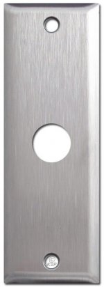
narrow, stainless steel wall plates ($6.95 ea) with a round hole in the center. I need to enlargen the hole to accommodate the switch body and I need to source some matching wood thread screws as I can't use the machine thread screws that were supplied as I'm mounting the wall plates directly to wood (cabinet stiles in 3 cases).
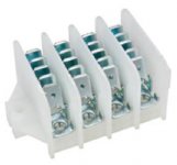
To streamline all the electrical connections, I decided to buy a Faston 4-pole, 5-position terminal strip. I sourced this via eBay UK ($12.79).
With all the parts now in-hand, it was time to use a VOM (volt, ohm meter) to detemine what pins were for what on the switches. More often than not, items I've ordered that have shipped from China come with zero documentation. Last night, I was able to sketch out a circuit and do a sort of bread board test. Success after a few bad starts.
Today, I spent time measuring wire lengths required for 2 of my 5 runs. I made up the wiring assemblies for those 2 runs and wired the relay to the terminal strip.
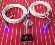
Time to test! Using an 110 VAC to 12 VDC power supply, I successfully tested the circuit with the first 2 switch assemblies. Ya!
I plan to make up the final 3 switch assemblies, then packup all the gear into the RV for installation in the near future. When this project is complete, I'll photos of the installed switches and relay/terminal strip.
This could just be one of the few projects I do that Nancy "really gets" and feels she benefits from it. Some of the other projects I do are a bit obscure and seem to benefit only me

I've attached a schematic in the event anyone wants to try this using the same switch and relay I used.
Below is a quick video showing a successful bench test of the curcuit with the first 2 switch assemblies. Note how when switch is used to activate the circuit, the light turns on, on all the switches. Exactly what I was looking for.
 let alone do it.
 I think I'll send a PM to Dave and tell him he needs to extend his Rally a couple more weeks just so I can keep you captive with all the questions I have (or will come up with between now and the end of the week.)
 Thanks

