- Home
- Forums
- HEARTLAND RVs GENERAL AREA
- Appliances - For all Heartland brands
- Refrigerators
- Gas Absorption Refrigerators (2-way & 3-way)
You are using an out of date browser. It may not display this or other websites correctly.
You should upgrade or use an alternative browser.
You should upgrade or use an alternative browser.
Dometic fridge fans
- Thread starter CTD2005
- Start date
NWILSON
Kentucky Chapter Leaders - retired
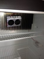
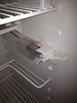
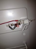
Here are some pics of the installation:


There is a "piggyback" connector that comes with the kit. Just clip the red wire to the proper length and crimp the connector to it. The power lead to the light switch is then attached to the "piggyback" and the "piggyback" is connected to the switch. ( Don't substitute my simplified directions for the manufacturer's supplied instructions!)


There is a "piggyback" connector that comes with the kit. Just clip the red wire to the proper length and crimp the connector to it. The power lead to the light switch is then attached to the "piggyback" and the "piggyback" is connected to the switch. ( Don't substitute my simplified directions for the manufacturer's supplied instructions!)
wesley1963
Wes
Thanks for the photos, however the lite is different in the RM 1350
Hey Gene,
I installed one on a 1350. The lens on ours has a simple tab on the bottom of the lens that squeezes upward and the lens pops off.
For20hunter
Pacific Region Directors-Retired
Has anyone used these fans on the Norcold side by side refridgerator and if so how did it work? Did it make as big of a cooling difference as it does on the Dometics?
Rod Ditrich
Sent from my GT-P5113 using Tapatalk 4 Beta
Rod Ditrich
Sent from my GT-P5113 using Tapatalk 4 Beta
wesley1963
Wes
I got the lens off. but is at a lose to how to remove the housing from its position to get to the wiring!
There's no need to get to the wiring. Just remove the bulb and hold the fan wire against the rear bulb contact and reinstall the bulb.
danemayer
Well-known member
Has anyone used these fans on the Norcold side by side refridgerator and if so how did it work? Did it make as big of a cooling difference as it does on the Dometics?
Rod Ditrich
Sent from my GT-P5113 using Tapatalk 4 Beta
Rod,
The improvement comes from better circulation of cold air air inside the frig, so it should help any make/model, assuming it fits on the fins and you can tap off the light bulb or other voltage source. It's inexpensive enough to take a risk. If it doesn't fit, I'm sure you there'd be someone at an upcoming rally who would love to take it off your hands.
mrcomer
Past Ohio Chapter Leaders (Founding)
There's no need to get to the wiring. Just remove the bulb and hold the fan wire against the rear bulb contact and reinstall the bulb.
While this will work, it will only work when the door is open and the light turns on. The fans really need to run when the door is shut for better circulation.
danemayer
Well-known member
Mark,While this will work, it will only work when the door is open and the light turns on. The fans really need to run when the door is shut for better circulation.
Are you sure the back of the bulb doesn't have constant voltage?
danemayer
Well-known member
If you take a reading with the door open, it's hot. If you take a reading with the door closed....well, that's the same problem as checking to see if the light really goes out when the door closes.
I was having trouble with the light 18 months ago and looked at the schematic. It was not completely clear to me how the light circuit works (connections p6 and p7?), but I think there's voltage on one terminal of the lamp and the door switches provide a path to ground. If there's someone out there who is better at reading the attached schematic, I'd love to hear what you think.
I was having trouble with the light 18 months ago and looked at the schematic. It was not completely clear to me how the light circuit works (connections p6 and p7?), but I think there's voltage on one terminal of the lamp and the door switches provide a path to ground. If there's someone out there who is better at reading the attached schematic, I'd love to hear what you think.
Attachments
The schematic does show the door switches as providing a ground path for the lamp. i.e the lamp should be at +12v all the time. The switches also provide a ground input to the control board (via P7) for what reason, I do not know. Maybe it initiates the cooling circuit whenever the door is open in anticipation of the increased heat load.
If you take a reading with the door open, it's hot. If you take a reading with the door closed....well, that's the same problem as checking to see if the light really goes out when the door closes.
I was having trouble with the light 18 months ago and looked at the schematic. It was not completely clear to me how the light circuit works (connections p6 and p7?), but I think there's voltage on one terminal of the lamp and the door switches provide a path to ground. If there's someone out there who is better at reading the attached schematic, I'd love to hear what you think.
porthole
Retired
The way I read that schematic is P6 is supplying + to the bulb.
There are two switches (why?). When the switch closes the the bulb is grounded and lights.
Why P7? My guess is a signal to the circuit board. Perhaps to activate the fan when the door closes - that feature where the system pulls the door tight initially.
There are two switches (why?). When the switch closes the the bulb is grounded and lights.
Why P7? My guess is a signal to the circuit board. Perhaps to activate the fan when the door closes - that feature where the system pulls the door tight initially.
For20hunter
Pacific Region Directors-Retired
Good point Dan. I will order it now. 
Sent from my GT-P5113 using Tapatalk 4 Beta
Sent from my GT-P5113 using Tapatalk 4 Beta
porthole
Retired
I assume one switch for each door. Either switch closes the circuit.
Makes sense, wasn't thinking 2 doors - not having a 2 door refer ..................
Similar threads
- Replies
- 1
- Views
- 415
- Replies
- 0
- Views
- 1K
- Replies
- 10
- Views
- 19K
- Replies
- 9
- Views
- 2K
